
Composite materials

a technology of composite materials and composite materials, applied in the field of composite materials, can solve the problems of insufficient and poor electrical conductivity of composite materials based on fibre reinforcements, etc., to achieve the effect of improving electrical conductivity, improving electrical conductivity, and improving electrical conductivity

Inactive Publication Date: 2013-12-12
HEXCEL COMPOSITES LTD (GB)
View PDF6 Cites 19 Cited by
  • Summary
  • Abstract
  • Description
  • Claims
  • Application Information

AI Technical Summary

Benefits of technology

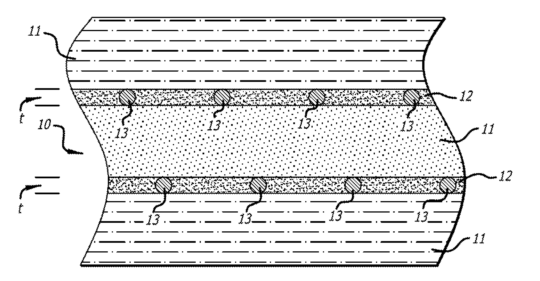
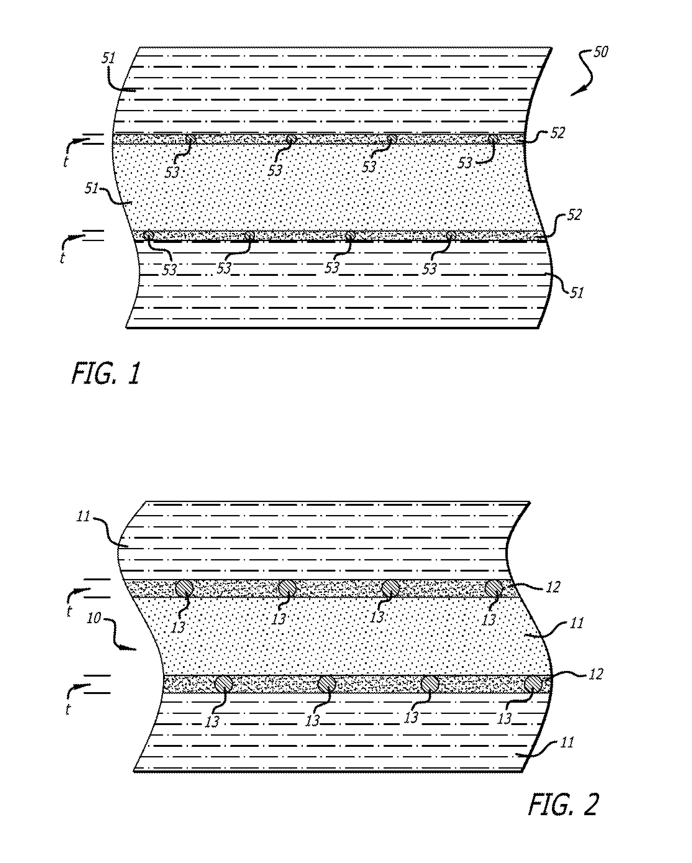
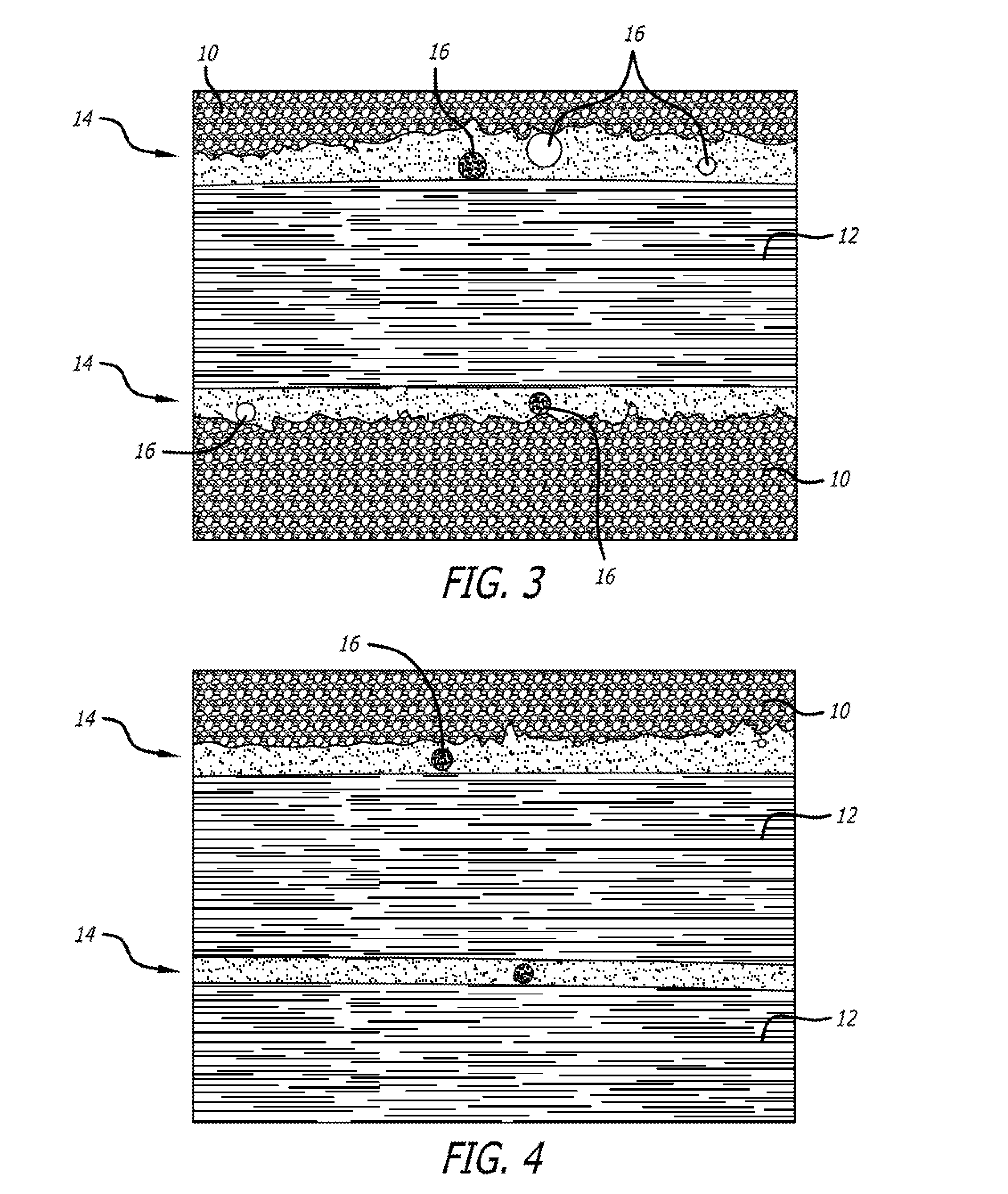
The solution provides enhanced electrical conductivity in the z-direction, improving lightning strike resistance and maintaining mechanical properties, with the use of glassy carbon particles acting as bridges between fibre layers to facilitate electrical connections across resin interleafs.

Problems solved by technology

However, whilst electrical conductivity is one of the most obvious attributes of metals, composite materials based on fibre reinforcements (such as adhesive films, surfacing films, and pre-impregnated (prepreg) materials), generally have much lower electrical conductivity.
Most early first generation matrix polymers for the manufacture of composites were, by nature, brittle and it has therefore been necessary to develop more toughened versions.
However, the level of electrical conductivity provided is insufficient for protecting the composite material from the damaging effects of, for example, a lightning strike.
However, they are generally heavy and have significantly degraded mechanical and aesthetic properties.
These composites are usually found at the first one or two plies of the material, and therefore a poor overall surface finish often results.
However, the conductivity pathway is only in the direction of the fibres, with limited ability for dissipation of electrical current in directions orthogonal to the plane of the fibre reinforcement (z direction).
Carbon reinforced materials often comprise an interleaf structure which results in inherently low conductivity in the z direction due to the electrical insulation properties of the interleaf.
The result of such an arrangement can lead to disastrous effects when damaged by lightning as the electrical discharge can enter the interleaf, volatilize the resin therein, and cause mass delamination and penetration through the composite material.
However, these resin layers act as an electrical insulator and therefore electrical conductivity in the z direction of the material is poor (i.e. orthogonal to the direction of the fibres).
Lightning strikes on the composite material can result in catastrophic failure of the component, with a hole being punched through a multiple ply laminate.

Method used


Image

  • Composite materials
  • Composite materials
  • Composite materials

Examples


example 7

Carbon Composite with Conductive Particles

[0165]M21 resin was modified with silver coated solid glass spheres (20 μm) at a range of 0.8-2.4 vol. % of the resin and the components were blended in a Winkworth mixer. The resin was coated as a thin film on silicone release paper and was then impregnated on intermediate modulus IM7 carbon fibre at a resin weight of 35% using a hot press to make a unidirectional prepreg. A five ply prepreg of approximately 10 cm by 10 cm was laid up unidirectionally and cured on a vacuum table at a pressure of 7 bar at 177° C. for 2 hours. A z-direction electrical resistance value was determined according to the method of Example 1. Results are summarised in Table 3.

TABLE 3Volume resistivity of carbon composite modified with silvercoated glass spheres.Silver coatedglass spheresSilver coated glassZ-direction volumeExample(vol. %)spheres (wt. %)resistivity (Ωm)6——3.667-10.822.137-21.641.897-32.461.75

[0166]The results in Table 3 clearly show a decrease in z-...

example 8

Carbon Composite with Conductive Particles

[0167]M21 resin was modified with silver coated hollow glass spheres (20 μm) at a range of 2.5-10.0 vol. % of the resin, and the components were blended in a Winkworth mixer. The resin was coated as a thin film on silicone release paper and was then impregnated on intermediate modulus IM7 carbon fibre at a resin weight of 35% using a hot press to make a unidirectional prepreg. A five ply prepreg of approximately 10 cm by 10 cm was laid up unidirectionally and cured on a vacuum table at a pressure of 7 bar at 177° C. for 2 hours. A z-direction electrical resistance value was determined according to the method of Example 6. Results are summarised in Table 4.

TABLE 4Volume resistivity of carbon composite modified with silvercoated hollow glass spheres according to Example 8.Silver coatedZ-directionSilver coated hollowhollow glassvolumeExampleglass spheres (vol. %)spheres (wt. %)resistivity (Ωm)8-12.52.50.1168-25.05.00.0648-37.57.50.0328-410.010....

example 9

Carbon Composite with Conductive Particles

[0169]M21 resin was modified with silver coated polymethylmethacrylate particles (20 μm) at a range of 2.5-10.0 vol. % of the resin. The resin was produced by blending the components in a Winkworth mixer. The resin was coated as a thin film on silicone release paper and was then impregnated on intermediate modulus IM7 carbon fibre at a resin weight of 35% using a hot press to make a unidirectional prepreg. A five ply prepreg of approximately 10 cm by 10 cm was laid up unidirectionally and cured on a vacuum table at a pressure of 7 bar at 177° C. for 2 hours. A z-direction electrical resistance value was determined according to the method of Example 6. Results are summarised in Table 5.

TABLE 5Volume resistivity of carbon composite modifiedwith silver coated PMMA spheres.Silver coatedSilver coatedPMMA particlesPMMA particlesZ-direction volumeExample(vol. %)(wt. %)resistivity (Ωm)9-12.52.50.5679-25.05.00.1039-37.57.50.1109-410.010.00.052

[0170]T...


PUM

PropertyMeasurementUnit
weight %aaaaaaaaaa
thicknessaaaaaaaaaa
sphericityaaaaaaaaaa

Abstract

A composite material, the composite material comprising at least one prepreg, said prepreg comprising at least one polymeric resin and at least one fibrous reinforcement; and glassy carbon particles dispersed in the polymeric resin.

Description

[0001]This application is a continuation of co-pending U.S. application Ser. No. 13 / 390,142, which was filed on Feb. 13, 2012. This application is also a continuation-in-part of co-pending U.S. application Serial 12 / 221,635, which was filed on Aug. 8, 2008 and which is a continuation of PCT / GB2007 / 004220 filed Nov. 3, 2007.BACKGROUND OF THE INVENTION[0002]1. Field of the Invention[0003]The present invention relates to composite materials, and particularly, but not exclusively, to fibre reinforced composite materials.[0004]The present invention relates to improvements in the electromagnetic response of composite materials, particularly to providing improved resistance to damage caused by lightning strikes.[0005]2. Description of Related Art[0006]Composite materials are increasingly used in structural applications in many fields owing to their attractive mechanical properties and low weight in comparison to metals. Composites are known in the field to consist of layering of materials ...

Claims


Application Information

Patent Timeline
Patent Type & Authority Applications(United States)
IPC IPC(8): B32B5/16B32B37/14
CPCB32B5/16B32B37/14B32B5/26B32B27/12B32B27/20B32B27/38B32B2250/20B32B2260/023B32B2260/046B32B2262/106B32B2264/0214B32B2264/0264B32B2264/108B32B2264/12B32B2307/202B32B2605/18C08J2363/00C08J2477/02Y10T428/24372Y10T156/10Y10T428/249924C08J5/243C08J5/249B32B5/22B32B5/28B32B5/30C08J5/06C08J5/10
Inventor CAWSE, JOHNSIMMONS, MARTINGREEN, GEORGE
Owner HEXCEL COMPOSITES LTD (GB)
Learn More