

Driving device for vibration-type actuator and medical system using same
a technology of driving device and actuator, which is applied in the direction of piezoelectric/electrostrictive device details, instruments, applications, etc., can solve the problems of inability to employ electromagnetic motors, difficult to fully remove harmonic noise in driving waveform, and mixed noise in mr images
- Summary
- Abstract
- Description
- Claims
- Application Information
AI Technical Summary
Benefits of technology
Problems solved by technology
Method used
Image

Examples
first embodiment
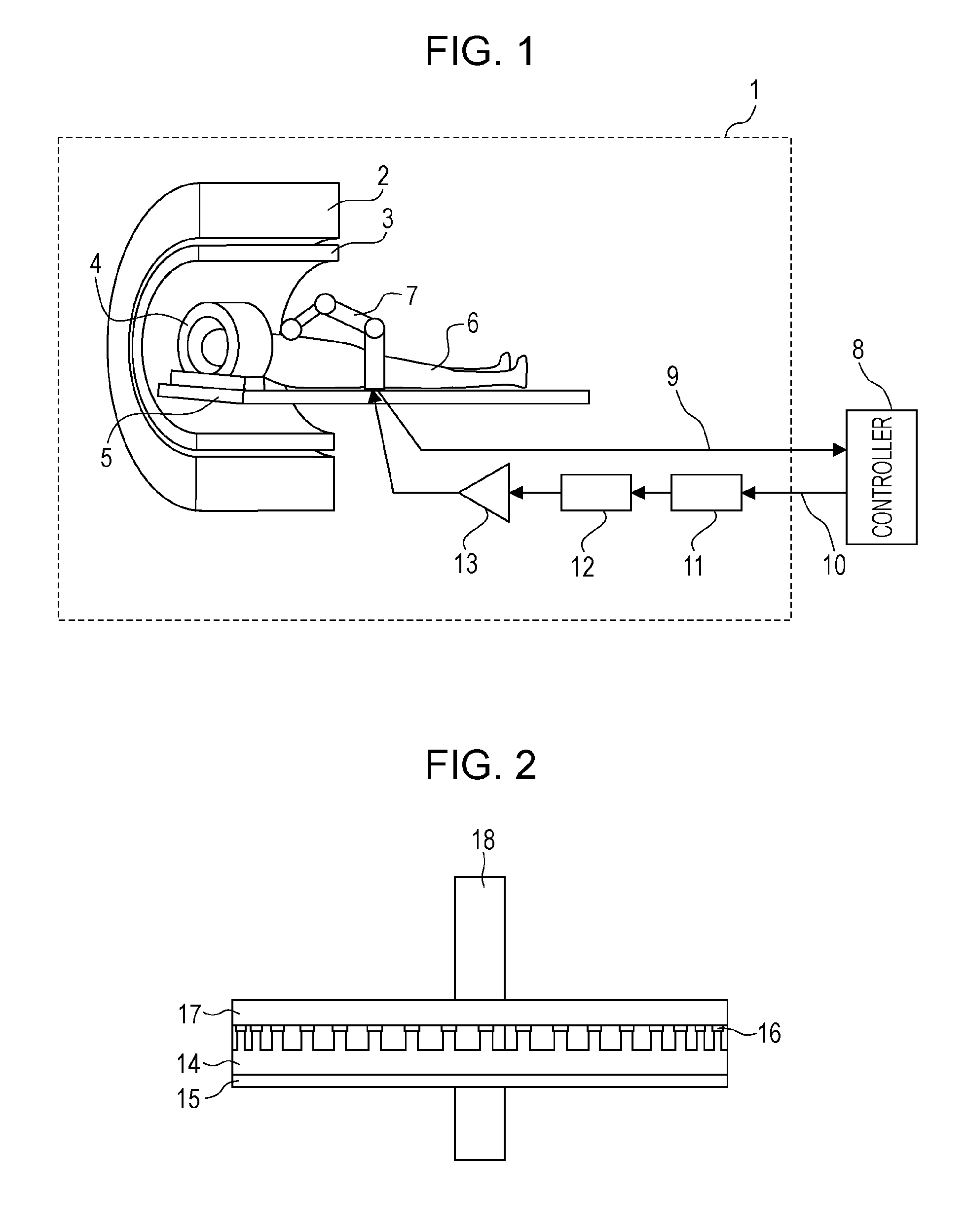
[0032]FIG. 1 is a diagram that illustrates a configuration of a medical system according to a first embodiment of the present disclosure. This system performs functional magnetic resonance imaging (fMRI). fMRI is a technique of visualizing changes in blood flow caused by brain and spine activity using an MRI apparatus. This system changes a contact stimulus on a time-series basis by moving a robotic arm using a vibration-type actuator and measures corresponding changes in blood flow inside the brain. Aside from a contact stimulus, various types of stimuli, such as a visual one and an auditory one, are studied as the stimulus used in the system. In particular, when a robotic arm or another tool is moved inside the MRI apparatus, electromagnetic noise produced by a driving source is reduced by magnetically shielding, and members are demagnetized to minimize distortion of a static magnetic field.
(Basic Configuration of MRI Apparatus)
[0033]First, the configuration of a system that inclu...
second embodiment
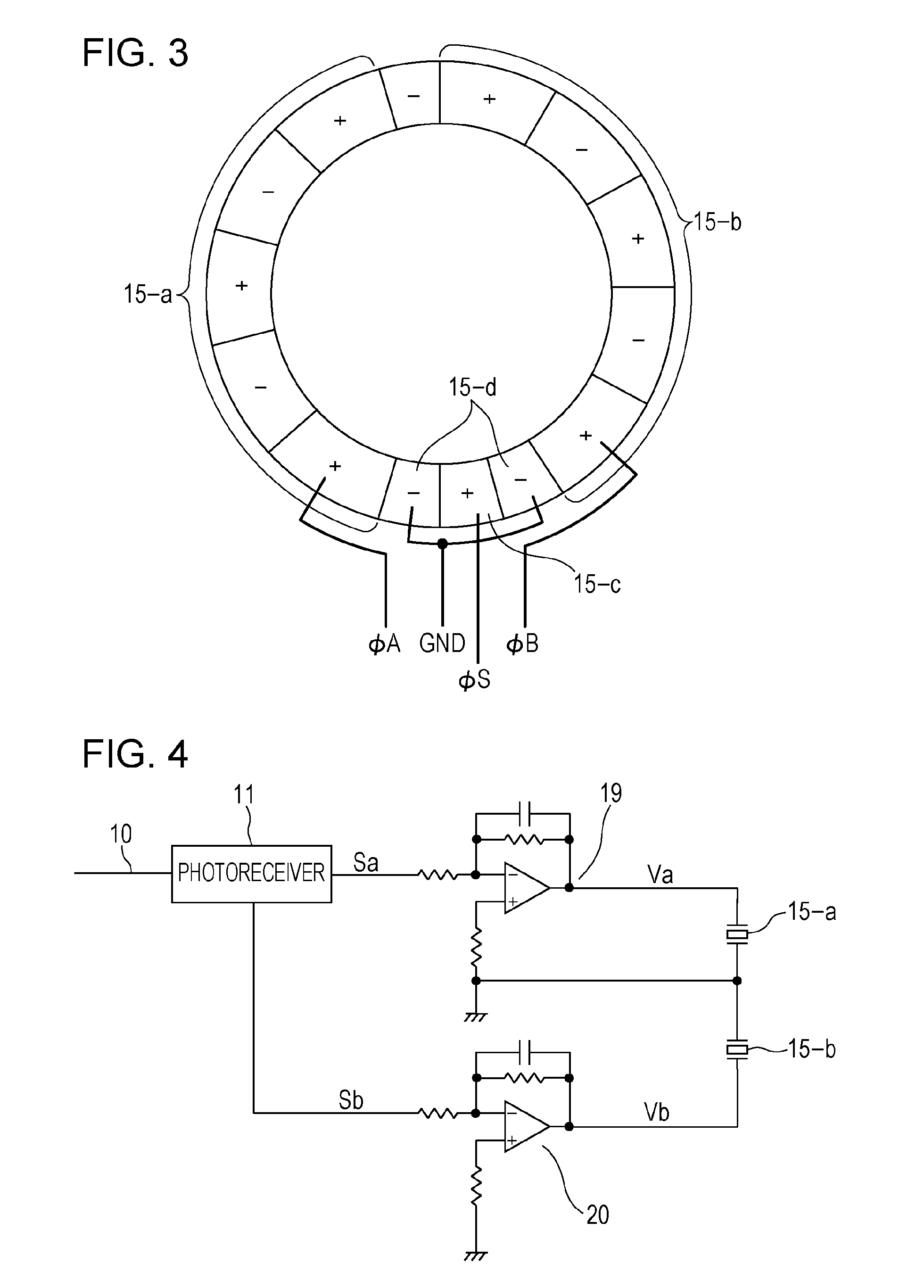
[0071]A second embodiment of the present application is described next. FIG. 10 illustrates a driving circuit for a vibration-type actuator according to the second embodiment. In the present embodiment, transformers are disposed between the linear amplifiers 19 and 20 and the electrodes 15-a and 15-b of the piezoelectric member 15 of the vibration-type actuator, and the circuit is insulated from the ground. That is, the primary sides of the transformers are connected to the linear amplifiers, whereas the secondary sides of the transformers are connected to the vibration-type actuator. Driving voltages output from the linear amplifiers are applied to the vibration-type actuator through the transformers. Thus common-mode noise mixing through the power supply lines of the linear amplifiers 19 and 20 can be prevented to some extent from entering the vibration-type actuator.
[0072]The configuration of the driving circuit illustrated in FIG. 10 is the one in which transformers 40 and 41 ar...
third embodiment
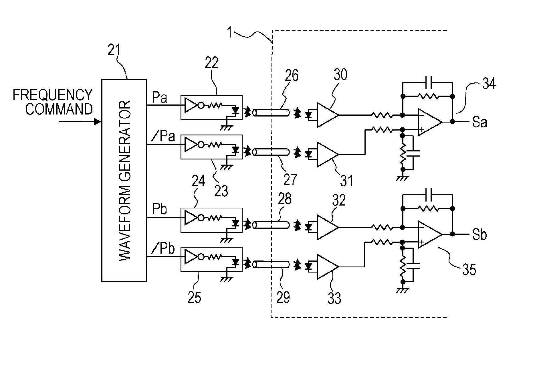
[0086]A third embodiment of the present application is described next. FIG. 18 illustrates a driving circuit for a vibration-type actuator according to the third embodiment. In the present embodiment, the inside and outside of the magnetically shielded room 1 are connected using optical fibers, and a driving signal for the vibration-type actuator and an encoder signal for use in detecting a rotation position are transmitted using optical signals.
[0087]A speed control unit 46 detects a rotation speed that indicates a driving state of a vibration-type actuator 57 from a rotary encoder 52 in response to a speed command from an output signal of a command unit (not illustrated), and controls any one of a frequency, amplitude, and phase of an alternating voltage to be applied to the vibration-type actuator 57. The speed control unit 46 is disposed inside the controller 8 illustrated in FIG. 1. That is, the speed control unit 46 is disposed outside the magnetically shielded room 1, and is ...
PUM
 Abstract
Description
Claims
Application Information