Optical component and display

Active Publication Date: 2013-12-19
SHARP KK
View PDF7 Cites 22 Cited by
  • Summary
  • Abstract
  • Description
  • Claims
  • Application Information

AI Technical Summary

Benefits of technology

[0034]The main advantage of the invention is that the 2D mode of the display is made especially uniform due to the diffusive action of the microlenses in their 2D mode. This is important because for main stream display acceptance 3D displa

Problems solved by technology

The switchable parallax barriers have the disadvantage that they are inefficient in 3D mode (reducing transmission by −65%).
This is a major disadvantage if the display is mostly used as a 3D display such as for a 3D camera.
In addition the 3D quality is not optimal.
It also has disadvantages that the system is more complicated to manufacture, and it may be very difficult to match the refractive index of the lens structure with the refractive index of the liquid crysta

Method used


Image

  • Optical component and display
  • Optical component and display
  • Optical component and display

Examples


embodiment 1

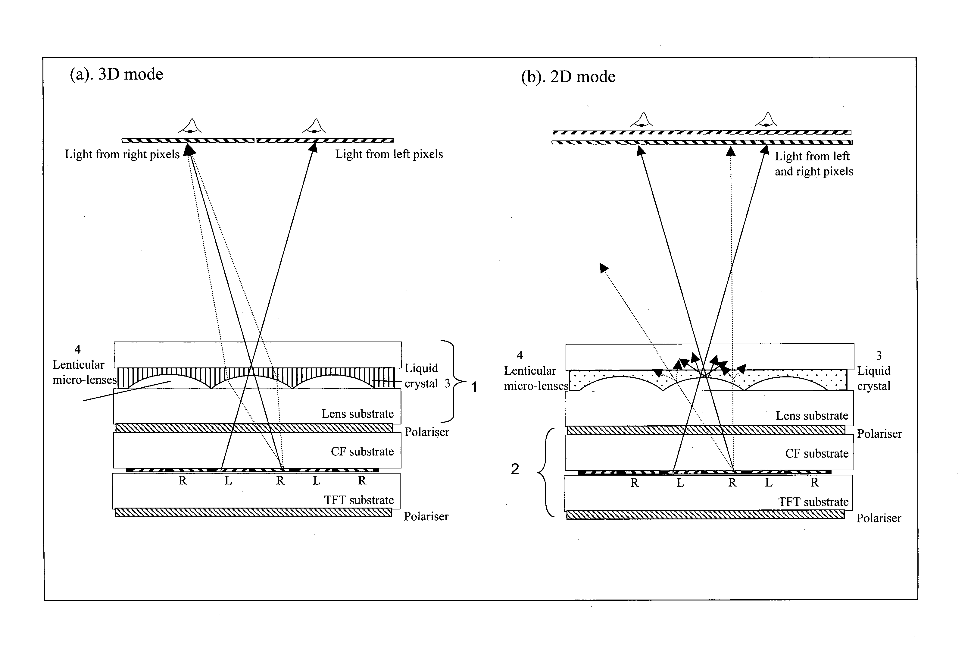
[0042]Embodiment 1 is described in the basic concept of the invention, and shown in FIGS. 3(a) and 3(b). This shows an optical component 1 having an array of microlenses 4. The microlenses are disposed on a substrate, and are planarised with an electro-optic layer, in this embodiment a LC layer 3. FIGS. 3(a) and 3(b) show the array of microlenses 4 being fully planarised by the LC layer 3—that is, the thickness of the liquid crystal layer is greater than (or equal to) the maximum thickness of the microlenses array—although in principle the invention could be effected with only partial planarisation of the microlenses (that is, with the thickness of the liquid crystal layer being less than the maximum thickness of the microlenses array). Electrodes (not shown) are positioned so that a voltage may be applied across the LC layer 3 to change its optical properties. The optical component 1 is positioned in the path of light from an image display panel 2.

[0043]The liquid crystal layer 3 i...

embodiment 2

[0050]A diagram of embodiment 2 is sketched in FIGS. 4(a) and 4(b). These again show a display formed of a switchable optical component 1 disposed over an image display panel 2.

[0051]The optical component 1 again has an array of microlenses 4, whose curved surfaces are at least partially planarised in with an electro-optic layer, in this example a LC layer 3 (FIGS. 4(a) and 4(b) show the LC layer 3 fully planarising the microlenses 4). Electrodes are positioned so that a voltage may be applied across the LC layer 3 to change its optical properties, as shown in the enlarged partial views of FIGS. 4(c) and 4(d).

[0052]The liquid crystal layer 3 is placed over the curved surfaces of the microlenses 4. The liquid crystal layer 3 may be placed directly against the curved surfaces of the microlenses, or there may be one or more components between the liquid crystal layer 3 and the curved surfaces of the microlenses (such as, for example an alignment layer and / or an electrode layer). Howeve...

embodiment 3

[0063]In a further embodiment the shape of the lens may be a Fresnel lens, as shown in FIG. 5. The main advantages of this are that the LC cell can be thinner, so less LC (or other electro-optical material) is needed to reduce cost, and the LC may switch between 2D and 3D modes faster. This embodiment may be combined with any one of the embodiments previously described herein—that is, the lens of any previous embodiment may be embodied as a Fresnel lens

[0064]Although certain preferred embodiments of the invention have been described above, the invention is not limited to the described embodiments and other variations are possible.

[0065]As an example, in the embodiments described above the lenses are embossed in a plastics sheet, but the invention is not limited to this. The directional effect of a black mask in a nominally non-directional mode described with reference to FIGS. 4a and 4b will occur in other switchable components, and the invention may for example be applied to other ...


PUM


Abstract

An optical component (1) is switchable between a directional mode and a 2-D mode. The optical component (1) comprising a lens array and an electro-optic layer, for example a liquid crystal layer, disposed in the path of light through the lens array. In the 2-D display mode the lens array has an optical effect on light passing through the component and the electro-optic layer at least partially nullifies the effect. For example the electro-optic layer may, in the 2-D display mode, scatter light or diverge light so as to nullify the focusing effect of the lens array. The optical component (1) may be disposed in the path of light through an image display panel (2) to form a display that may be switched between a directional display mode, eg a 3-D display mode, and a 2-D display mode by suitably switching the optical component (1).

Description

TECHNICAL FIELD[0001]This invention relates to multi-view displays such as autostereoscopic displays, multiple view displays such as dual view displays, and directional displays which change their appearance depending on the angle from which they are viewed.BACKGROUND ART[0002]For many years people have been trying to create better stereoscopic 3D displays, and this invention provides a further advance in this field.[0003]A stereoscopic display gives the illusion of depth in the image by giving each eye a different perspective of a scene, as would happen in reality. The brain then fuses these perspectives together to form a 3D representation of the image in the brain. For example, this may be done by displaying one perspective with one polarisation, and the other perspective in a different polarisation. A viewer can then see stereoscopic depth by wearing glasses where each eye piece only allows the appropriate polarisation to pass.[0004]An auto-stereoscopic display is a display that...

Claims


Application Information

Patent Timeline
IPC IPC(8): G02F1/29G02B27/22
CPCG02F1/29G02B27/2214G02F1/1323G02F1/133526H04N13/31H04N13/356G02F1/133562H04N13/305G02B30/27
Inventor MATHER, JONATHANSMITH, NATHAN JAMES
Owner SHARP KK
Why Eureka
Try Eureka