Eureka AIR delivers breakthrough ideas for toughest innovation challenges, trusted by R&D personnel around the world.

Apparatus and method for defect detection including patch-to-patch comparisons

a technology of apparatus and defect detection, applied in the analysis of microscopic patterned objects or articles, can solve the problems of achieve the effects of reducing noise in the defect detection process, improving sensitivity, and improving distinction

Active Publication Date: 2013-12-19
APPL MATERIALS ISRAEL LTD
View PDF7 Cites 21 Cited by
  • Summary
  • Abstract
  • Description
  • Claims
  • Application Information

AI Technical Summary

Benefits of technology

The present invention relates to a method for detecting defects in microscopic objects. The technical effects of this invention are as follows: 1. By comparing microscopic object locations to references that differ from the location being inspected, defect detection is carried out by reducing noise. 2. Intra-frame comparisons, in which frames of same die are compared, provide a more similar reference, reducing noise in the defect detection process. This increases sensitivity to better distinguish between real defects and false alarms. 3. In die-to-die (D2D) applications, wherein the distance between locations being compared may be relatively large, noise levels are significantly lower than inter-die detection, allowing better sensitivity to detect defects. 4. In die-to-model (D2M) applications, instead of comparing an image to the model, the image is compared to itself, resulting in far superior sensitivity, relative to conventional methods where the image and model often differ significantly. 5. In scenarios where no reference is available, including creating a new reference from other patches in the image being inspected, very sensitive detection can be facilitated.

Problems solved by technology

Detection is carried out by comparing microscopic object locations to references which differ from the location that is being inspected, causing noise in the defect detection process.
In classic D2D detection, defect detection includes inter-frame comparisons of microscopic object locations which are relatively far away, relative to the scope or size of local differences, causing noise in the defect detection process.

Method used


Image

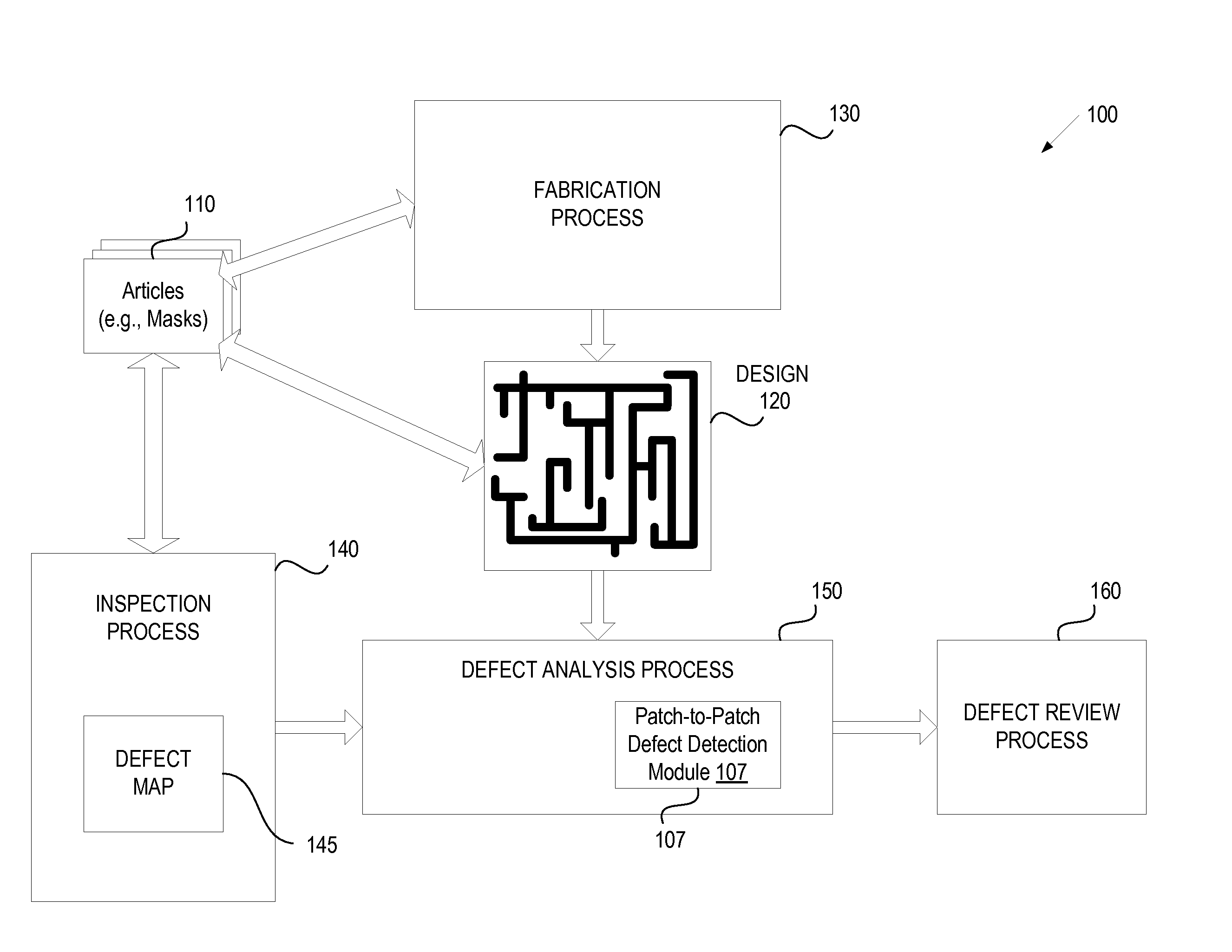
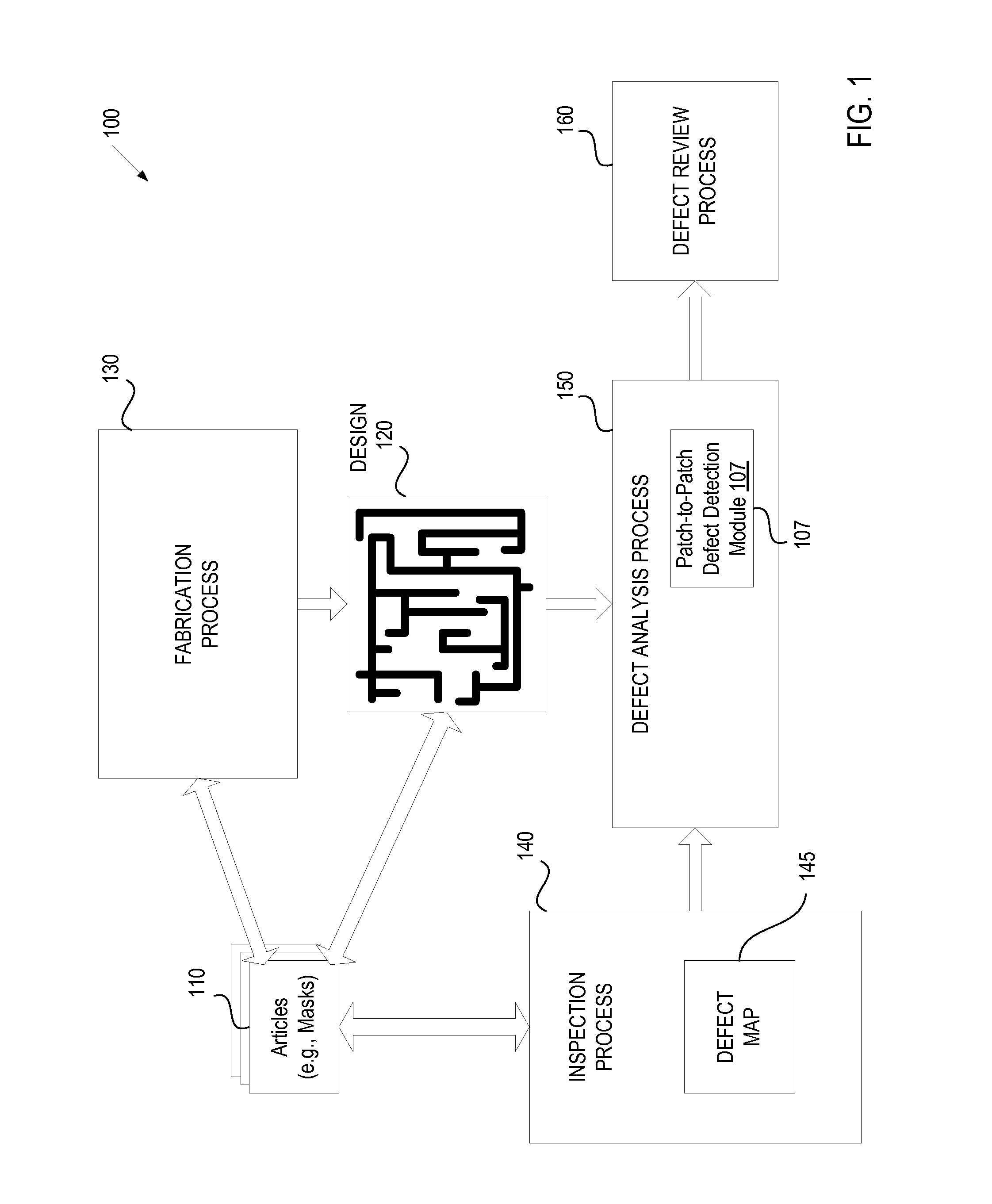
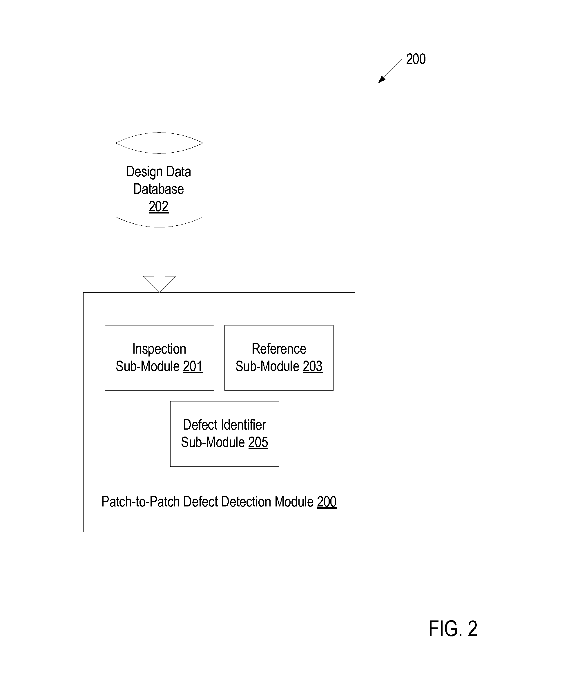
  • Apparatus and method for defect detection including patch-to-patch comparisons
  • Apparatus and method for defect detection including patch-to-patch comparisons
  • Apparatus and method for defect detection including patch-to-patch comparisons

Examples


example 1

Dynamic Bounding Box Motivation

[0136]Candidate's bounding box accuracy depends on the funnel performance. Certain funnels may yield relative inaccurate bounding boxes for defects, especially large defects. A possible way to compute the defect's score (SNR) is as follows: P2P score=Difference within bounding box / std of difference pixels outside bounding box. The defect may not be entirely contained in the bounding box computed by Candidate Analysis step 210 described herein. Therefore, there may be defective pixels outside the bounding box. If estimating noise STD according to defective pixels in which the difference signal is significantly higher than regular noise pixels, an over-estimation of the noise STD (denominator in the P2P score computation) May result. Therefore, the P2P score of large defects tends to be lower than the ‘true’ score.

example 2

Another Example Motivation

[0137]A possible attribute to be computed for each defect is its energy, typically defined as the squared sum of the SNR signal over all of the defect's pixels. Energy scoring may be performed in the energy detection (e.g., as described at block 1209 in FIG. 12). If the defect's contour is inaccurate, true defective pixels may be left out of this computation, or non-defective pixels may be erroneously included in this computation, yielding a less-than-optimal accuracy of the estimated energy signal. Therefore, the true contour of the defect is typically sought before computing the SNR signal. This may be done by finding irregular pixels connected to the original bounding box, thereby correctly determining the P2P score thus enabling reliable detection of large defects.

[0138]It is appreciated that, in certain embodiments, shallow defects tend to be relatively weak, but spread over a large are. A detection mechanism based on strongest difference pixel may cau...


PUM


Abstract

A system receives, based on processing of an inspected frame of an inspected image generated by collecting signals indicative of a pattern on an article, at least one candidate defect location in the inspected frame. The system defines a candidate patch within the inspected frame. The candidate patch is associated with the candidate defect location. The system identifies at least one similar patch in the inspected frame using a predefined similarity criterion and determines whether a defect exists at the candidate defect location based on a comparison of at least a portion of the candidate patch with at least a corresponding portion of the at least one similar patch.

Description

FIELD OF THE INVENTION[0001]The present invention relates generally to analysis of microscopic patterned objects or articles and more particularly to inspecting the surface of an article for defects and detection of defects.BACKGROUND OF THE INVENTION[0002]A common problem of defect detection is distinguishing between defects and noise. Typically, detection of defects on semiconductor masks, reticles and wafers is done by comparing an image of a portion of an article (e.g., mask, reticle or wafer) with a reference image. In a Die-to-Model method, the presence or absence of a defect in a location is checked by comparing the pattern at the desired location at an inspected die with the pattern of the same location in a model, prepared based on, for example, die design data or a model of inspected die / s. In the Die-to-Die method, the presence or absence of a defect in a location is checked by comparing the pattern at the desired location at an inspected die with the pattern of the same ...

Claims


Application Information

Patent Timeline
Patent Type & Authority Applications(United States)
IPC IPC(8): G06K9/00
CPCG06T7/001G06T2207/30141G06T2207/30148
Inventor DALLA-TORRE, MICHELESHERMAN, BORISHADAD, ZIONDANINO, YEHUDA UDYBULLKICH, NOGA
Owner APPL MATERIALS ISRAEL LTD
Why Eureka
Eureka Blog
Learn More