
Multi-Mode Separation for Target Detection and Cell Growth Monitoring

a target detection and cell growth technology, applied in the field of multi-mode separation for target detection and cell growth monitoring, can solve the problems of limited specificity, non-target capture, and high chance of non-specific binding, and achieve the effects of improving sensitivity, improving test sensitivity, and prolonging binding tim

Active Publication Date: 2013-12-19
RGT UNIV OF MICHIGAN
View PDF3 Cites 17 Cited by
  • Summary
  • Abstract
  • Description
  • Claims
  • Application Information

AI Technical Summary

Benefits of technology

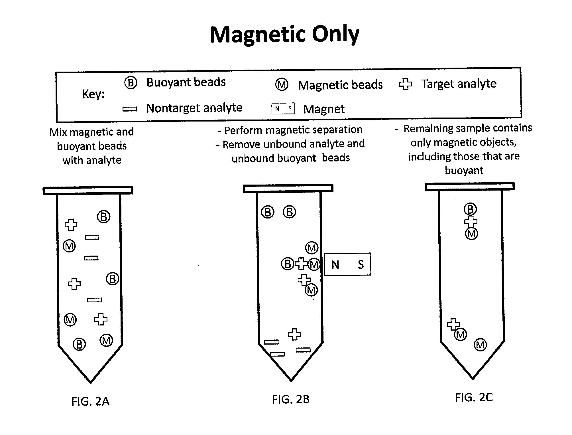
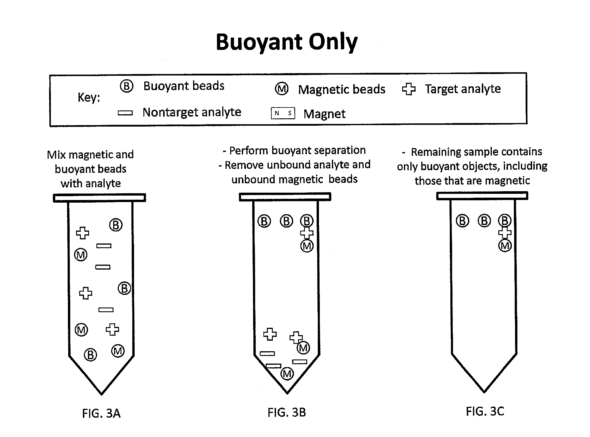
The patent describes a technique for separating two types of beads using a magnetic field and a buoyant force. This technique can be used to remove empty beads and visualize the two bead complexes based on their physical properties. After separation, the beads can be removed to leave only the target of interest. This technique allows for increased specificity and improves the accuracy of downstream analysis.

Problems solved by technology

A limitation that magnetic separation faces is that the specificity of the separation is governed by the specificity of a single antibody or other bead coating.
This limitation stems from the fact that magnetic separation uses a single mechanism (i.e. magnetic forces) to separate the beads with bound target from the rest of the sample.
Therefore, it leads to limited specificity and also to a high chance of non-specific binding.
This can result in non-targets being captured, which can affect methods like cell culturing or PCR, where non-targets can cause false positives or inhibit reactions.
Also in food testing, the presence of inhibiting agents binding to magnetic beads may limit the amount of initial sample that can be used for a PCR reaction.
Furthermore, because performing separation on a single physical mechanism allows for specificity from only a single biomolecule or coating (i.e. a single antibody), existing separation methods are not being used as visual assays.
However, lateral flow assays also have limitations in both the amount of sample that can be used (for example 100 μL) and the resulting sensitivity of the method.
Also, the line that indicates the presence of a target can be difficult to read.
Finally, lateral flow assays are one of the few methods that can be performed as a one-step assay; however, they don't necessarily utilize magnetic separation and the advantages that separation provides, including the ability to use larger initial amounts of sample.

Method used


Image

  • Multi-Mode Separation for Target Detection and Cell Growth Monitoring
  • Multi-Mode Separation for Target Detection and Cell Growth Monitoring
  • Multi-Mode Separation for Target Detection and Cell Growth Monitoring

Examples


example separation

Devices

[0105]FIGS. 22-24 illustrate different example separation devices as may be used to implement the present techniques. FIG. 22 illustrates a separation device 1000, which may use a disposable or reusable fluidic chamber. A sample inlet 1001 is coupled to channel 1002 connecting to a first separation chamber 1003, e.g., that is configured to separate unlabeled cells or debris from the rest of the sample (e.g. magnetic beads, buoyant beads, two-bead complexes). In the illustrated example, a magnet 1004 is positioned adjacent to the chamber 1003 and creates a gradient so that magnetic beads flow with the floating fraction (e.g. an upward magnetic force) in the chamber 1003. The chamber 1003 has a branching split so that floating and magnetic fraction continues into the next separation chamber 1008, through a channel 1007, while everything else flows to channel 1005 to an outlet (or reservoir) 1006 for sample measurement and / or testing, or for discarding.

[0106]The separation chamb...


PUM

PropertyMeasurementUnit
volumesaaaaaaaaaa
diameteraaaaaaaaaa
diameteraaaaaaaaaa

Abstract

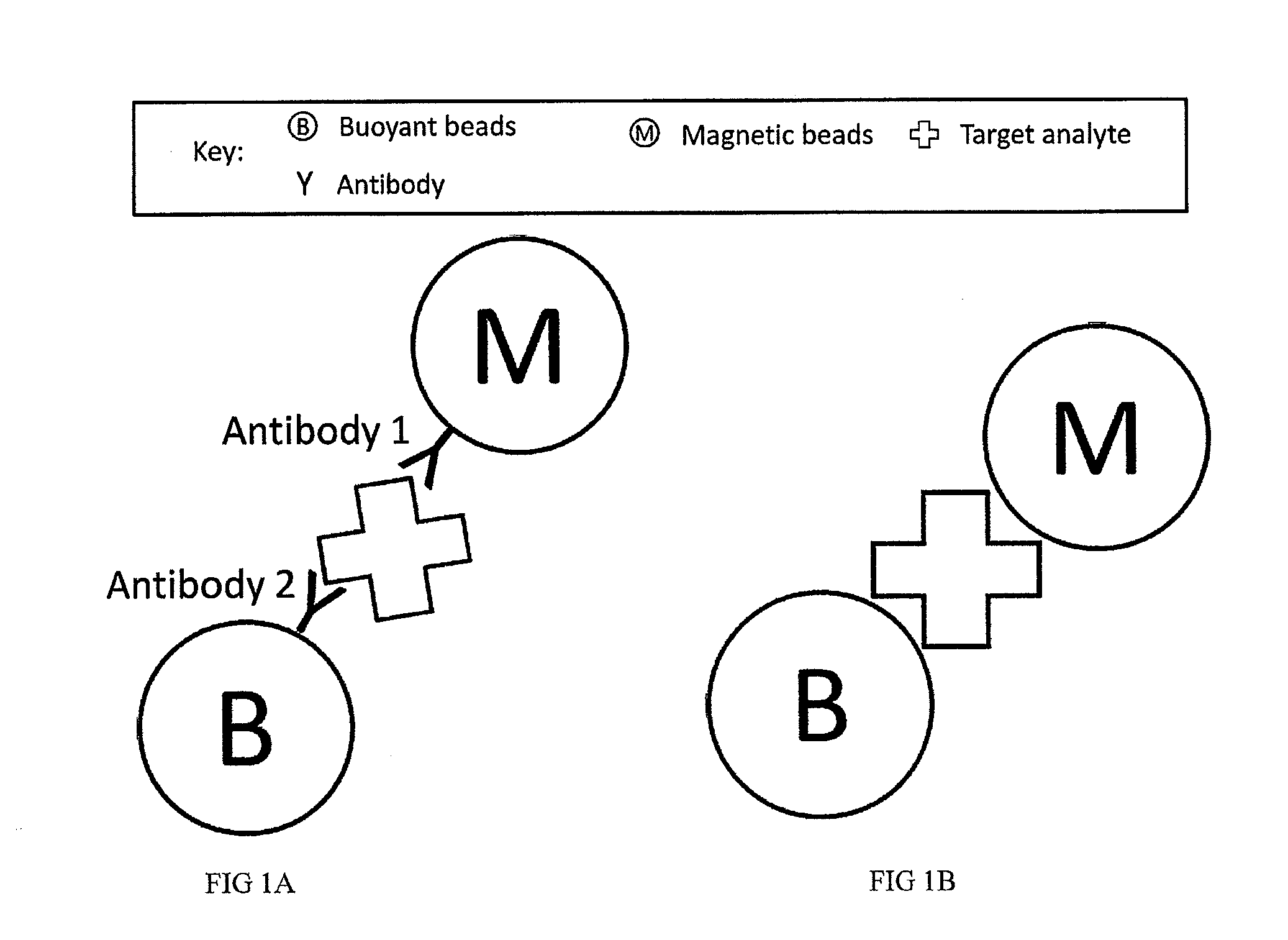
Sandwich separation is based on forming a sandwich complex with a magnetic bead, buoyant bead, and a target. Once a sandwich formation is created, the sandwich can be separated using its dual physical properties, namely magnetism and buoyancy. Sandwich separation is highly specific, allows for removal of the beads that do not have any attached target, and reduces the number of background beads. Sandwich separation can also be used to allow for target detection in raw specimen. Also, improvement of detection capability is accomplished by performing AMBR measurements on a solid interface, where the rotational period speeds up and allows for dramatically reduced time-to-result.

Description

CROSS REFERENCE TO RELATED APPLICATIONS[0001]The present application claims the benefit of U.S. Provisional Application No. 61 / 642,305, entitled “Highly Specific Sandwich Separation and Standard Well Plate Operation for Analyte Detection and Cell Growth Monitoring,” filed on May 3, 2012, which is hereby incorporated by reference in its entirety.FIELD OF THE INVENTION[0002]Described herein are methods, systems, reagents and devices for performing separation using two physical processes and for measuring and / or characterizing a target using asynchronous magnetic bead rotation on a solid interface.BACKGROUND OF THE INVENTION[0003]In the last thirty or so years, there have been dramatic changes in both sample preparation and testing procedures for numerous applications, including immunoassays, molecular diagnostics, medical microbiology, cell-based assays, and more. Inherent in many of these practical applications are some type of target isolation or separation and some type of target d...

Claims


Application Information

Patent Timeline
Patent Type & Authority Applications(United States)
IPC IPC(8): G01N1/30
CPCG01N1/30B03C1/01B03C1/288B03C2201/18B03C2201/26C12Q1/6804C12Q1/6816G01N33/54326G01N33/54366C12Q2563/143C12Q2563/149C12Q2565/101
Inventor MCNAUGHTON, BRANDON H.KINNUNEN, PAIVOYOUNGER, JOHN G.
Owner RGT UNIV OF MICHIGAN
Learn More