
Cooled magnet motor

a magnet motor and cooling technology, applied in the direction of dynamo-electric machines, magnetic circuit rotating parts, magnetic circuit shapes/forms/construction, etc., can solve the problem of windings becoming even hotter, and achieve the effect of reducing the thermal resistance in the path and further improving the cooling effect of the magnets

Active Publication Date: 2013-12-26
HDD SERVO MOTORS
View PDF3 Cites 19 Cited by
  • Summary
  • Abstract
  • Description
  • Claims
  • Application Information

AI Technical Summary

Benefits of technology

The patent text describes a technical solution for reducing the risk of demagnetisation of rotor magnets in an electric motor. The solution involves using a cooling fluid to cool down the magnets, which can help to prevent damage to the motor. The volume of the cooling fluid is chosen so that there is always fluid in the gap between the rotor and stator, even when the pressure inside the motor is very low and there is no possibility of leakage through the shaft seals. Overall, this solution helps to improve the reliability and performance of electric motors.

Problems solved by technology

This will cause the winding to become hotter, which will increase the winding resistance, causing the windings to become even hotter, etc.

Method used


Image

  • Cooled magnet motor
  • Cooled magnet motor
  • Cooled magnet motor

Examples


Embodiment Construction

[0043]In the following, a detailed description of the invention will be given. It will be appreciated that these figures are for illustration only and are not in any way restricting the scope of the invention.

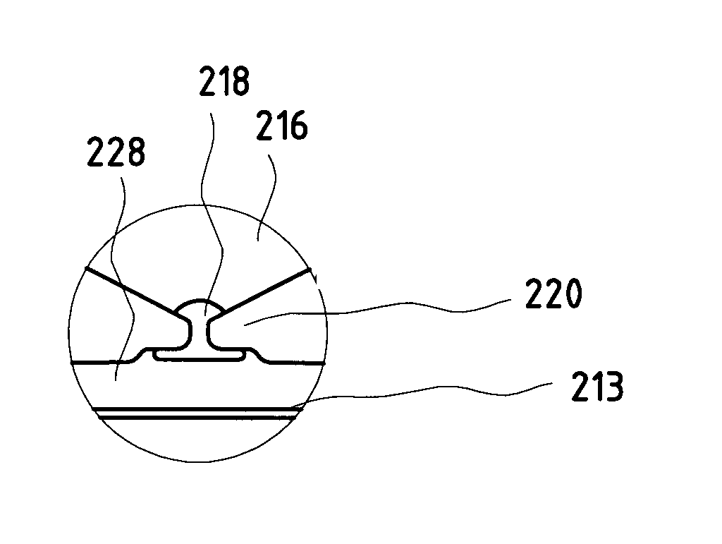
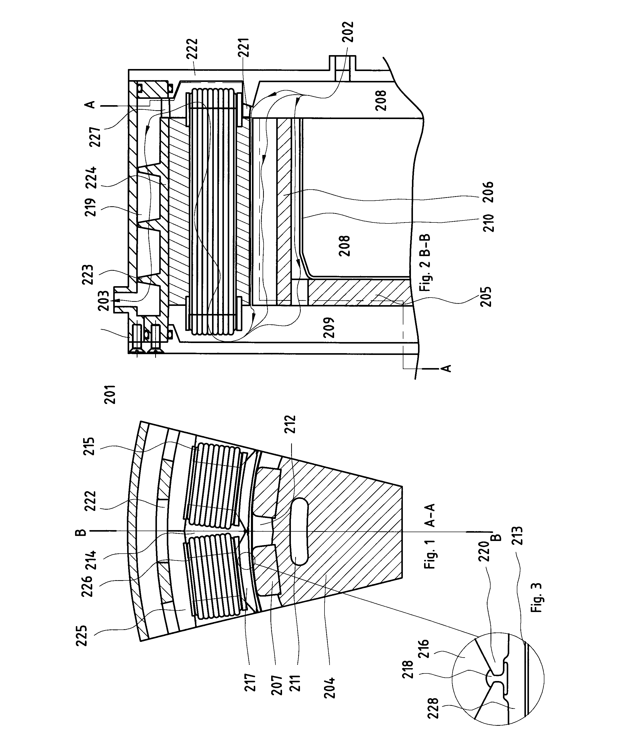
[0044]FIG. 1 shows a section A-A perpendicular to the axis of the motor or generator shown in FIG. 2.

[0045]FIG. 2 shows a section B-B parallel with the axis of the same permanent magnet motor / generator 201. The magnets have a very high BH product and a limited ability to withstand high stator currents at high temperatures. The cooling of the magnets is performed by a stream of cooling fluid that after entering into the motor / generator is led to the rotor magnet channels through a path (202-208) that does not cause any substantial heating of the fluid.

[0046]The fluid follows the path indicated by the thin line from 202 to 203. The rotor 204 has disc shaped part 205 and a hollow cylindrical part 206 on which the magnets 207 are assembled.

[0047]The cooling fluid can pass from the ...


PUM


Abstract

An electric motor / generator comprises a rotor with magnets mounted on the surface of the rotor, the magnets facing the stator over a gap. The magnets have a very high flux density but a limited ability to withstand high stator currents at high temperatures, preferably magnets made of the N48H material. By providing rotor magnet cooling means that reduces the temperature of the magnets by a cooling fluid, use of magnets with lower maximum working temperature and higher flux density is permitted and thereby higher flux can be obtained from the magnets.

Description

TECHNICAL FIELD[0001]The invention is concerned with cooled electric motors and generators.BACKGROUND ART[0002]Electric generators and motors with permanent magnet rotors are often cooled by liquids in thermal contact with the stator. Most of the heat is generated in the iron stator poles, the stator winding and to a lesser extent the rotor magnets. The magnets are in most cases in the centre of the motor inside the stator. The heat is generated mostly in the stator between the magnets and the cooling mantle and the cooling takes place outside the stator. The temperature of the magnets is therefore high.[0003]The temperature of the magnets and windings affects the losses of the motor / generator in two ways. The temperature of the copper in the winding affects the resistance of the copper material as the resistance increases with temperature. Therefore, more heat is generated in a hot winding for a given current. If (which is normally the case) the heat from the winding increases the ...

Claims


Application Information

Patent Timeline
IPC IPC(8): H02K9/19H02K1/27
CPCH02K9/19H02K1/32H02K5/207H02K5/203
Inventor STRIDSBERG, LENNART
Owner HDD SERVO MOTORS
Learn More