
Communication device and antenna system therein

a communication device and antenna technology, applied in the field of communication devices, can solve the problems of increasing the size of the whole antenna system, reducing the efficiency of the antenna, and degrading the radiation performance, so as to achieve high isolation and maintain the general effect of antenna efficiency

Active Publication Date: 2013-12-26
ACER INC
View PDF5 Cites 10 Cited by
  • Summary
  • Abstract
  • Description
  • Claims
  • Application Information

AI Technical Summary

Benefits of technology

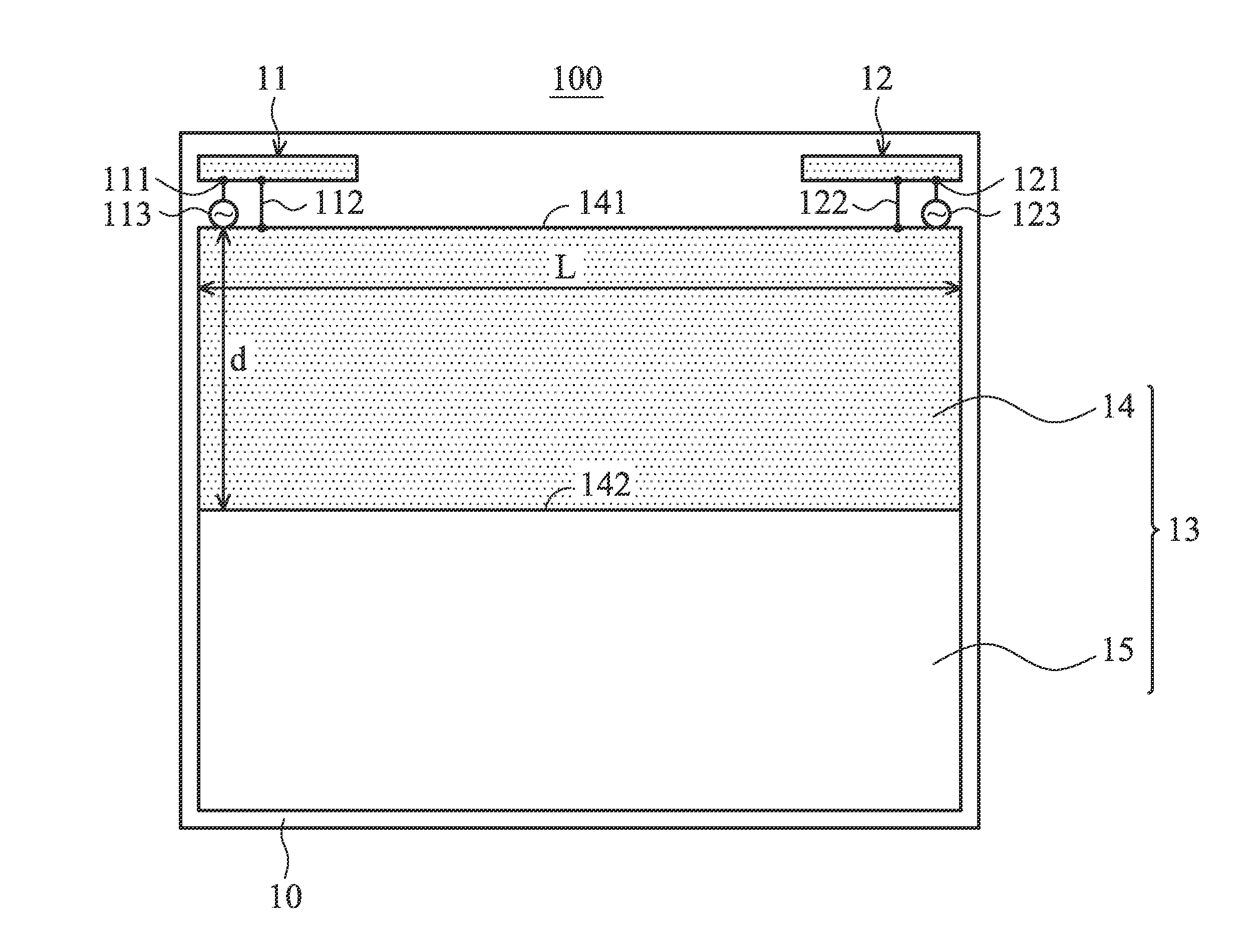
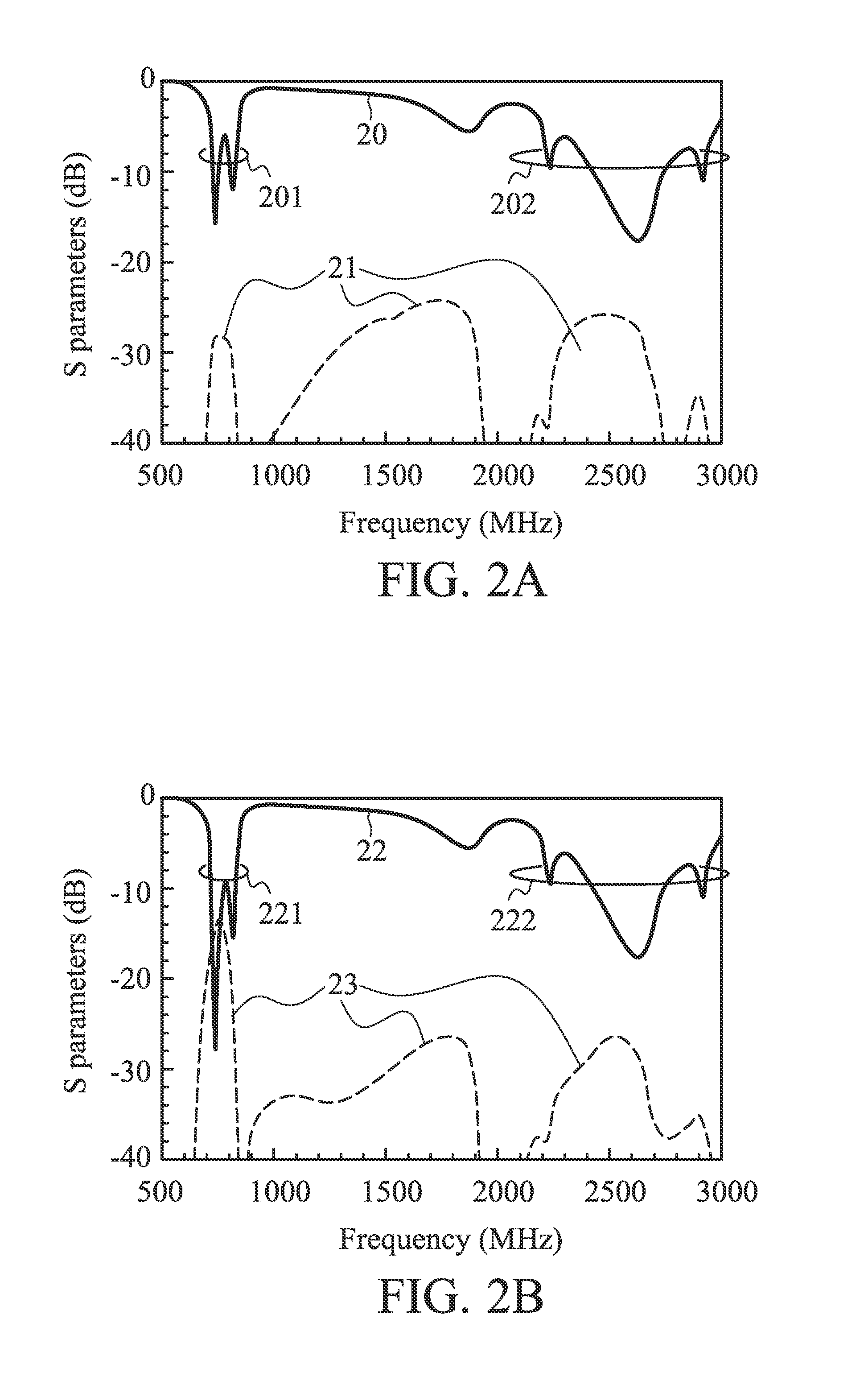
The invention is a new design for an antenna system that reduces surface currents and improves isolation between antennas. By integrating a non-conductive plate and a conductive plate, the system is more robust and efficient. The distance between the first edge of the conductive plate and the second edge is set to be about 0.25 wavelength of the lowest frequency in the first band. This design reduces mutual coupling between antennas and maintains the isolation between them. The increased isolation in the first band is about 15 dB or more.

Problems solved by technology

The drawbacks of the traditional method include decreased antenna efficiency and degraded radiation performance.
In addition, if these antennas are operated in an LTE 700 band (from 704 MHz to 787 MHz), the isolation element is required to resonate at about 700 MHz and hence requires a large element size, which greatly increases the size of the whole antenna system.
Integration of such an antenna system in the limited space inside the mobile device is a challenge for an antenna designer.

Method used


Image

  • Communication device and antenna system therein
  • Communication device and antenna system therein
  • Communication device and antenna system therein

Examples


Embodiment Construction

[0018]In order to illustrate the foregoing and other purposes, features and advantages of the invention, the embodiments and figures thereof in the invention are shown in detail as follows.

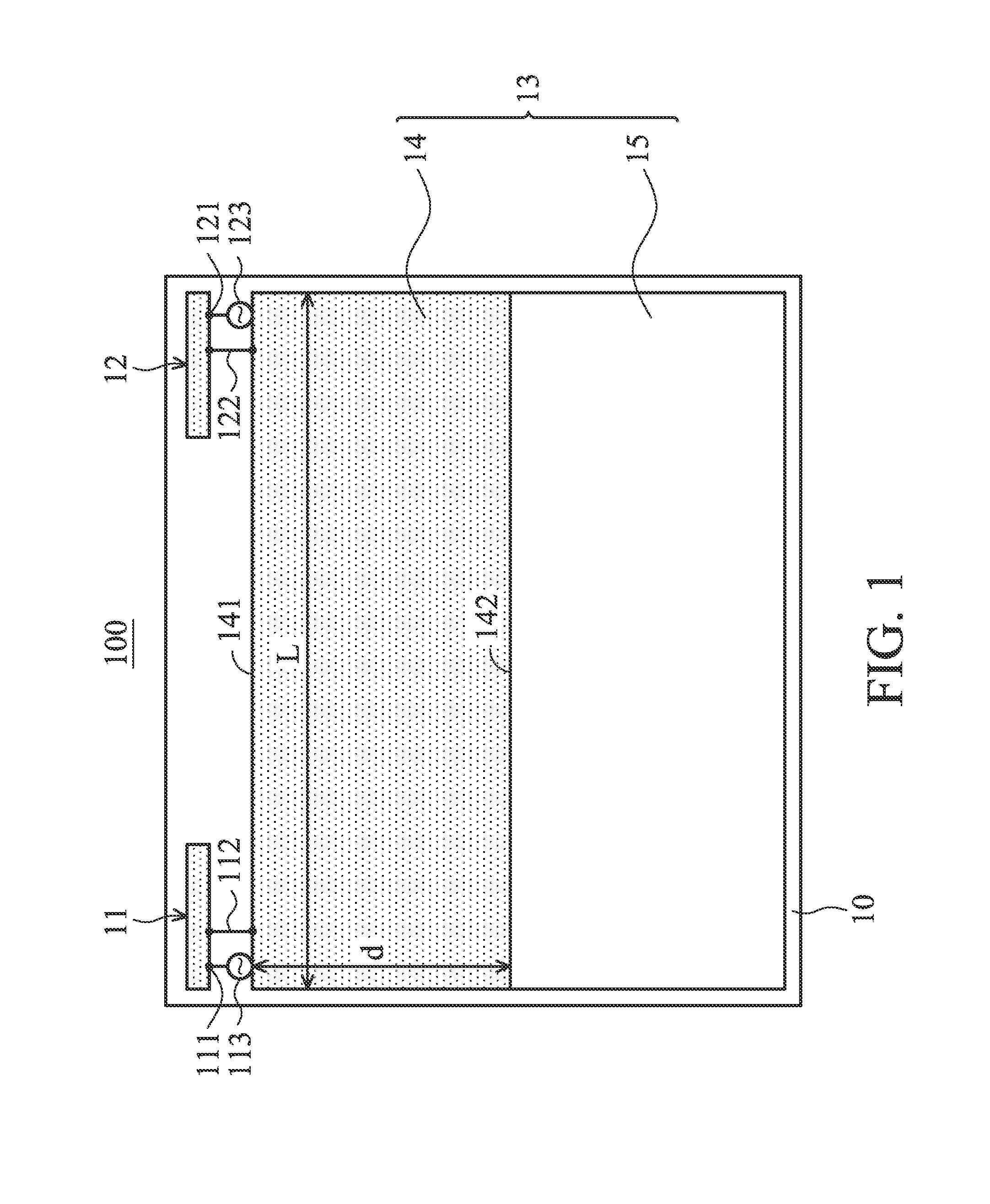
[0019]FIG. 1 is a diagram for illustrating a communication device 100 according to a first embodiment of the invention. In the first embodiment, the communication device 100 comprises a first antenna 11, a second antenna 12, and a supporting plate 13. The first antenna 11 and the second antenna 12 form an antenna system. The supporting plate 13 comprises a conductive plate 14 and a non-conductive plate 15. The conductive plate 14 has a first edge 141 and a second edge 142, wherein the second edge 142 is opposite to the first edge 141, and the second edge 142 is adjacent to the non-conductive plate 15. The first antenna 11 has a feeding terminal 111 and a shorting line 112. A signal source 113 is a feeding signal source of the first antenna 11. The shorting line 112 is electrically coupled to the c...


PUM


Abstract

A communication device including a supporting plate and an antenna system is provided. The supporting plate includes a conductive plate and a non-conductive plate. The conductive plate has a first edge and a second edge. The antenna system includes at least two antennas, which are both disposed at the first edge of the conductive plate and operate in at least a first band. A distance between the first edge and the second edge of the conductive plate is about 0.25 wavelength of the lowest frequency in the first band, and the distance is smaller than a length of the first edge.

Description

CROSS REFERENCE TO RELATED APPLICATIONS[0001]This Application claims priority of Taiwan Patent Application No. 101122355 filed on Jun. 22, 2012, the entirety of which is incorporated by reference herein.BACKGROUND OF THE INVENTION[0002]1. Field of the Invention[0003]The disclosure generally relates to a communication device, and more particularly, relates to a communication device comprising a MIMO (Multi-Input and Multi-Output) antenna system with high isolation.[0004]2. Description of the Related Art[0005]As people demand more and more data transmission, related communication standards are supporting higher and higher data transmission rates. For example, IEEE 802.11n can support MIMO technology to increase transmission rates. The related communication standards, such as LTE (Long Term Evolution), also support MIMO operations. As a matter of fact, it is a future trend to use multiple antennas in a mobile device. However, since multiple antennas are to be disposed in a limited spac...

Claims


Application Information

Patent Timeline
IPC IPC(8): H01Q21/00H01Q5/20
CPCH01Q1/2266H01Q1/38H01Q1/48H01Q1/521H01Q5/20H01Q9/42H01Q21/28H01Q21/30
Inventor WONG, KIN-LUWU, TSUNG-JU
Owner ACER INC
Learn More