Heat circulation pump

a circulation pump and heat exchange technology, applied in the direction of piston pumps, positive displacement liquid engines, liquid fuel engines, etc., can solve the problem of typically unusable lateral surfaces of motors, and achieve the effect of reducing manufacturing and assembly costs and saving large amounts

Active Publication Date: 2013-12-26
GRUNDFOS MANAGEMENT AS
View PDF6 Cites 19 Cited by
  • Summary
  • Abstract
  • Description
  • Claims
  • Application Information

AI Technical Summary

Benefits of technology

[0004]Such heating circulation pumps of smaller and medium construction type are manufactured on a large scale, which is why even the smallest of improvements could already lead to a large saving with regard to the manufacture and / or assembly. One constantly strives to improve these pumps on the one hand with regard to technology, and to design them such that they are more reliable, and on the other hand to lower the manufacturing and assembly costs.

Problems solved by technology

This region laterally of the motor is typically not usable in any case, since with modern permanent magnet motors which are constructionally long, the pump housing projects radially beyond the motor housing in this region and thus creates a free space which is unused and is thus available.

Method used


Image

  • Heat circulation pump
  • Heat circulation pump
  • Heat circulation pump

Examples


Embodiment Construction

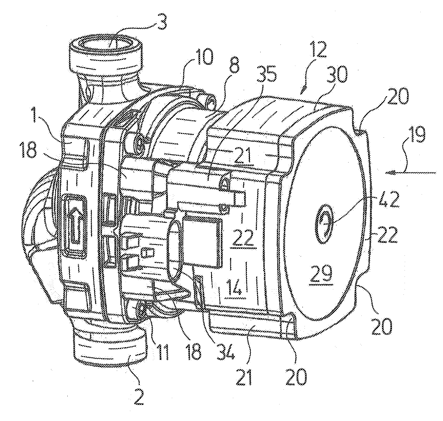
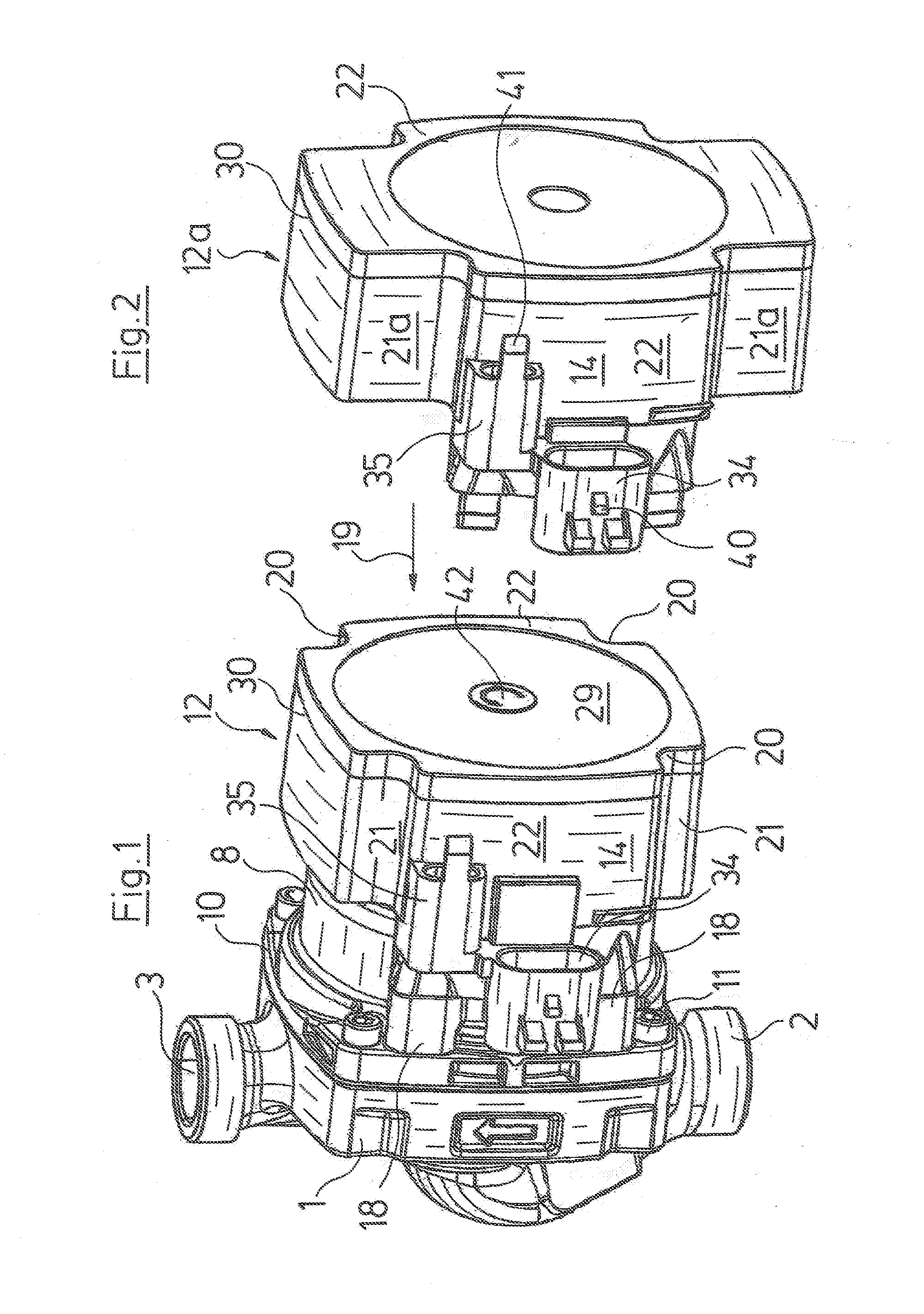
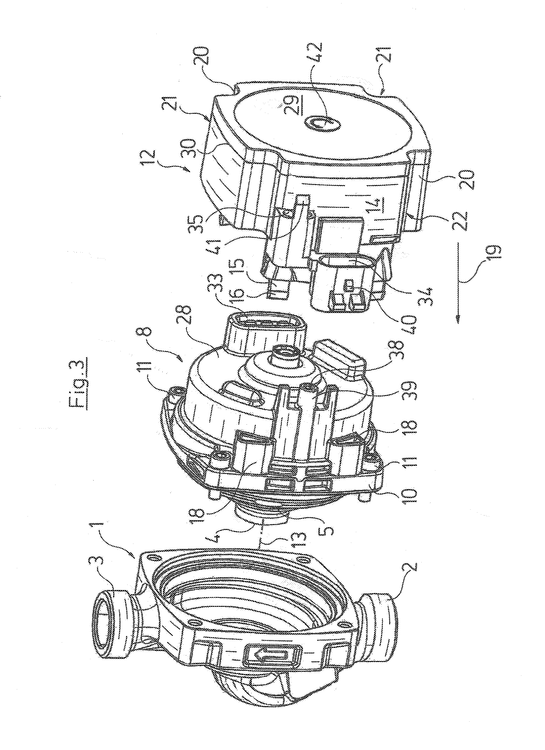
[0029]Referring to the drawings in particular, the heating circulation pump represented by way of FIGS. 1 and 3 to 8 comprises a centrifugal pump with a pump housing 1 with a suction connection 2 and a pressure connection 3 with a channel layout which is formed therebetween and which leads the fluid coning from the suction connection 2 to a suction port 4 of pump impeller 5 which is mounted within the pump housing 1 and whose driven side connects to a channel leading to the pressure connection 3.

[0030]The heating circulation pump moreover comprises a motor, here a wet-running motor, whose rotor 6 runs in a can 7 which is filled with fluid. The can 7 is surrounded by a stator, i.e. by the motor windings arranged on the peripheral side around the can 7, as well as by a motor housing 8 which accommodates the stator. The rotor 6 comprises a central shaft 9 which extends to into the pump housing 1 and carries the pump impeller 5, so that the rotation movement of the rotor 6 is transmitte...


PUM


Abstract

A heat circulation pump includes a pump housing (1) with a pump impeller arranged therein which is driven by an electric motor arranged in a motor housing (8) which axially connects to the pump housing (1). The heat circulation pump also includes a terminal box (12) which is axially connected to the motor housing (8) in order to receive electric and/or electronic components of the engine control. A plug or socket (34) of an electric plug connection is arranged on the outside of the terminal box (12) for the electric connection. The plug or socket (34) is/are axially offset with respect to the terminal box (12) and is/are arranged adjacent to the motor housing (8).

Description

CROSS REFERENCE TO RELATED APPLICATIONS[0001]This application is a U.S. National Phase Application of International Application PCT / EP2012 / 053222 filed Feb. 24, 2012 and claims the benefit of priority under 35 U.S.C. §119 of European Patent Application EP 11002071.6 filed Mar. 12, 2011, the entire contents of which are incorporated herein by reference.FIELD OF THE INVENTION[0002]The invention relates to a heating circulation pump with a pump housing with a pump impeller, which is arranged therein and which is driven by an electrical motor arranged in a motor housing connecting axially to the pump housing, with a terminal box connecting axially to the motor housing, for receiving electrical and / or electronic components of the motor control and with a plug or socket of an electrical plug connection for the electrical connection, the plug or socket being arranged outside on the terminal box.BACKGROUND OF THE INVENTION[0003]Such heating circulation pumps are counted as belonging to the ...

Claims


Application Information

Patent Timeline
Patent Type & Authority Applications(United States)
IPC IPC(8): F04D13/06
CPCF04D13/0693F04D13/0606F04D29/026F04D29/426H02K5/128H02K5/225H02K7/14F04D13/0686H02K11/33F05D2300/43F05D2230/20F04D13/0626
Inventor HOJ, FINN MATHIESENBLAD, THOMAS
Owner GRUNDFOS MANAGEMENT AS
Why Eureka
Try Eureka