Method and endoscopic device for examining or imaging an interior surface of a corporeal cavity

Inactive Publication Date: 2013-12-26
NANAMED
View PDF0 Cites 22 Cited by
  • Summary
  • Abstract
  • Description
  • Claims
  • Application Information

AI Technical Summary

Benefits of technology

[0038]In another embodiment of the invention, the imaging catheter includes an imaging element and an optional image axis changing element (e.g., a mirror, a prism). Optionally, these elements are aligned along the longitudinal axis of the shaft. Optionally, a number of optical elements, such as lenses and diffractive optics elements are positioned between the imaging element and the axis changing element. A potential advantage of such an arrangement is that the diameter of the endoscopic imaging catheter can be made small and/or substantially independent of the length of the optical distance between the imaging element and an imaged area. In other embodiments, the imaging element is pointed at a direction perpendicular to or obliq

Problems solved by technology

All these maneuvers of the endoscope prolong the procedure and cause added discomfort, complications, and risks to the patient.
The inability to obtain a retrograd

Method used


Image

  • Method and endoscopic device for examining or imaging an interior surface of a corporeal cavity
  • Method and endoscopic device for examining or imaging an interior surface of a corporeal cavity
  • Method and endoscopic device for examining or imaging an interior surface of a corporeal cavity

Examples


Embodiment Construction

[0131]Some embodiments of the invention are herein described, by way of example only, with reference to the accompanying drawings. With specific reference now to the drawings in detail, it is stressed that the particulars shown are by way of example and for purposes of illustrative discussion of embodiments of the invention. In this regard, the description taken with the drawings makes apparent to those skilled in the art how embodiments of the invention may be practiced.

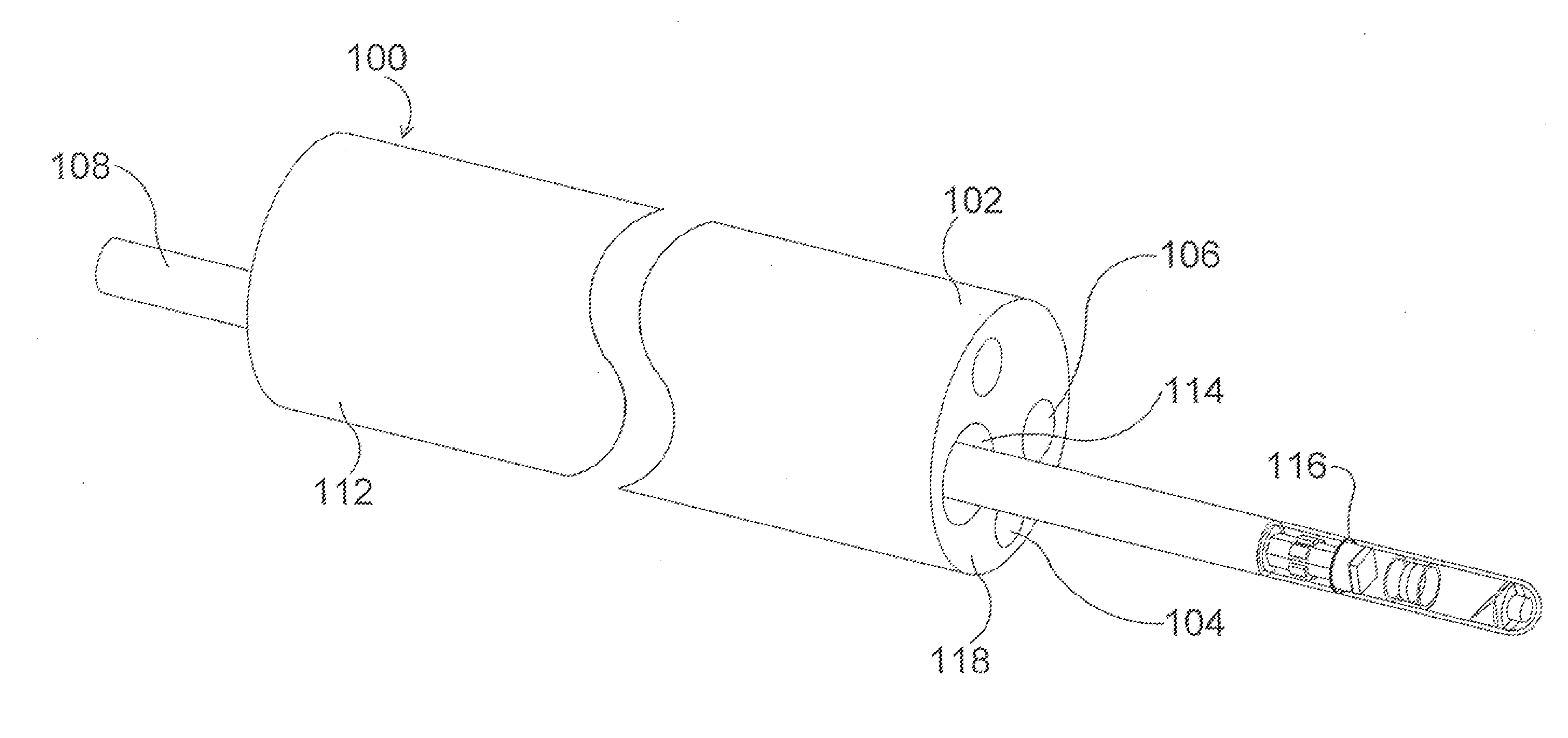
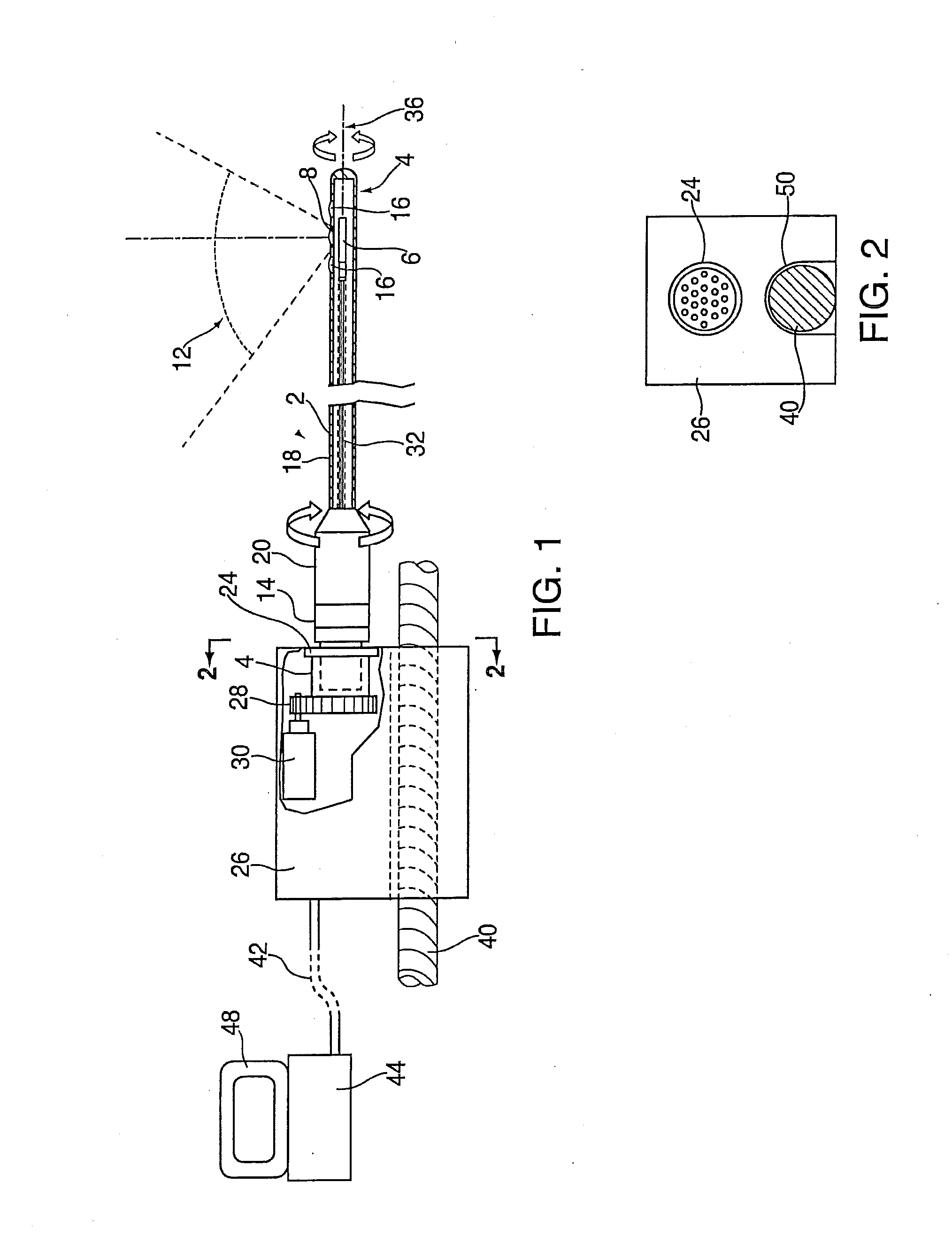
[0132]FIG. 1 shows a perspective view of an auxiliary endoscopic imaging catheter system according to one embodiment of the present invention. In this figure the entire auxiliary endoscopic catheter 2 rotates and / or wobbles. Catheter 2 comprises a sealed capsule 4 that comprises a camera 6 and side optical windows 8, which comprise a ring-like shape through the entire circumference of the capsule. Camera 6 is comprised of a single or multiple imaging sensor(s) (as CMOS or CCD) with its electronics as well as certain...


PUM


Abstract

An auxiliary endoscopic imaging catheter is configured for insertion via a longitudinal working channel of an endoscopic. The endoscopic imaging catheter comprises a longitudinally extending tubular shaft having a proximal end, a distal end, and outer surface, and a longitudinal axis; one or more transparent or translucent elements positioned in the outer surface of the distal end of the shaft; and an imaging system comprising a reflector/refractor element and an imaging sensor, the imaging system being positioned interior of the distal end of the shaft. The reflector/refractor can be rotated or wobbled to obtain images of up to or over 360°. An illumination system is positioned on or in the distal end of the shaft, the illumination system being capable of illuminating a corporeal lumen or organ adjacent to the distal end.

Description

CROSS-REFERENCE TO RELATED APPLICATION[0001]This application is a continuation-in-part of co-pending, commonly assigned U.S. patent application Ser. No. 13 / 104,915, filed May 10, 2011, which in turn is based upon and claims the benefit of the filing date of co-pending, commonly assigned U.S. Provisional Patent Application Ser. No. 61 / 333,214, filed May 10, 2010, incorporated herein by reference, each of which is incorporated herein in its entirety.FIELD OF THE INVENTION[0002]The present invention relates to an endoscope assembly. More particularly, the invention relates to an endoscopic imaging catheter with rearward-viewing capability and a method of performing a medical procedure.BACKGROUND OF THE INVENTION[0003]An endoscope is a medical or industrial device comprising a flexible or rigid tube and a camera or fiber optics mounted on the distal end or any other part close to the distal end of the tube. The endoscope is insertable into an internal body cavity through a body orifice ...

Claims


Application Information

Patent Timeline
IPC IPC(8): A61B1/00A61B1/06A61B1/018
CPCA61B1/00183A61B1/018A61B1/06A61B1/00172A61B1/00177A61B1/00096A61B1/0016A61B1/0125A61B1/0615A61B1/0676A61B1/0684A61B1/0655
Inventor HADANI, RON
Owner NANAMED
Why Eureka
Try Eureka