
Radiological image detection apparatus

a detection apparatus and radiological technology, applied in the direction of instruments, conversion screens, nuclear engineering, etc., can solve the problems of inability to determine crystallinity and the sensitivity of scintillators, and achieve excellent sensitivity

Inactive Publication Date: 2014-01-02
FUJIFILM CORP
View PDF2 Cites 9 Cited by
  • Summary
  • Abstract
  • Description
  • Claims
  • Application Information

AI Technical Summary

Benefits of technology

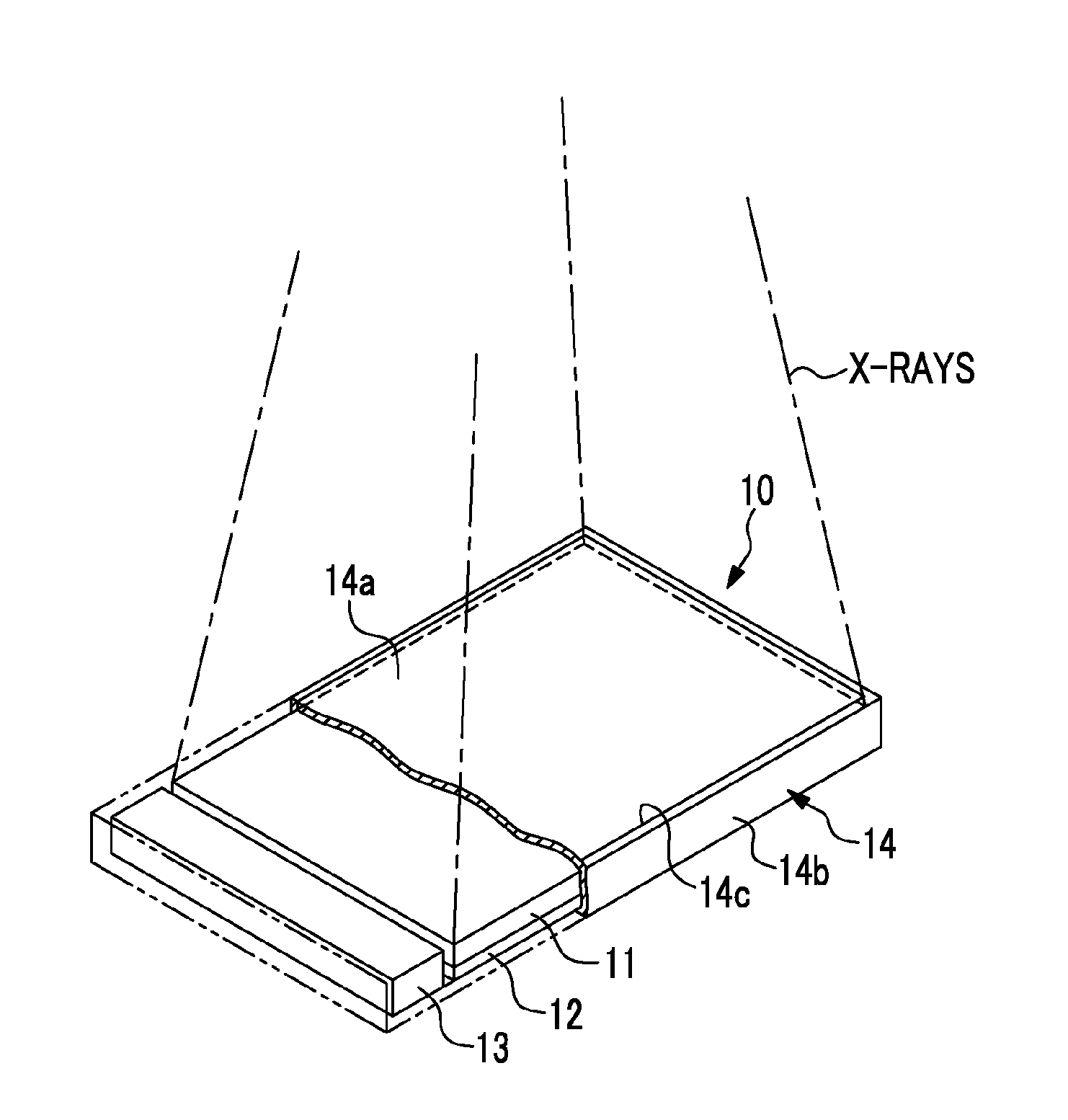
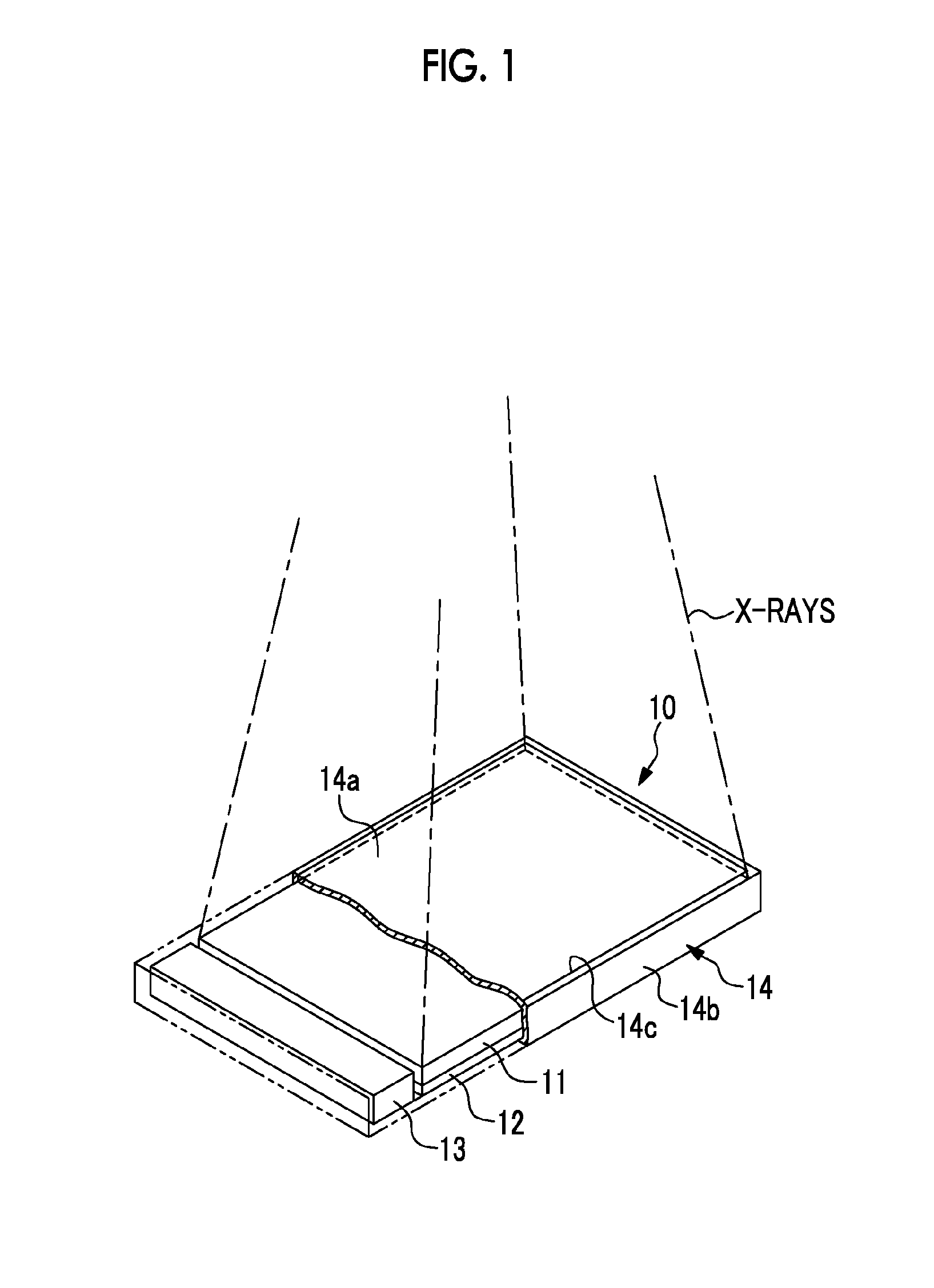
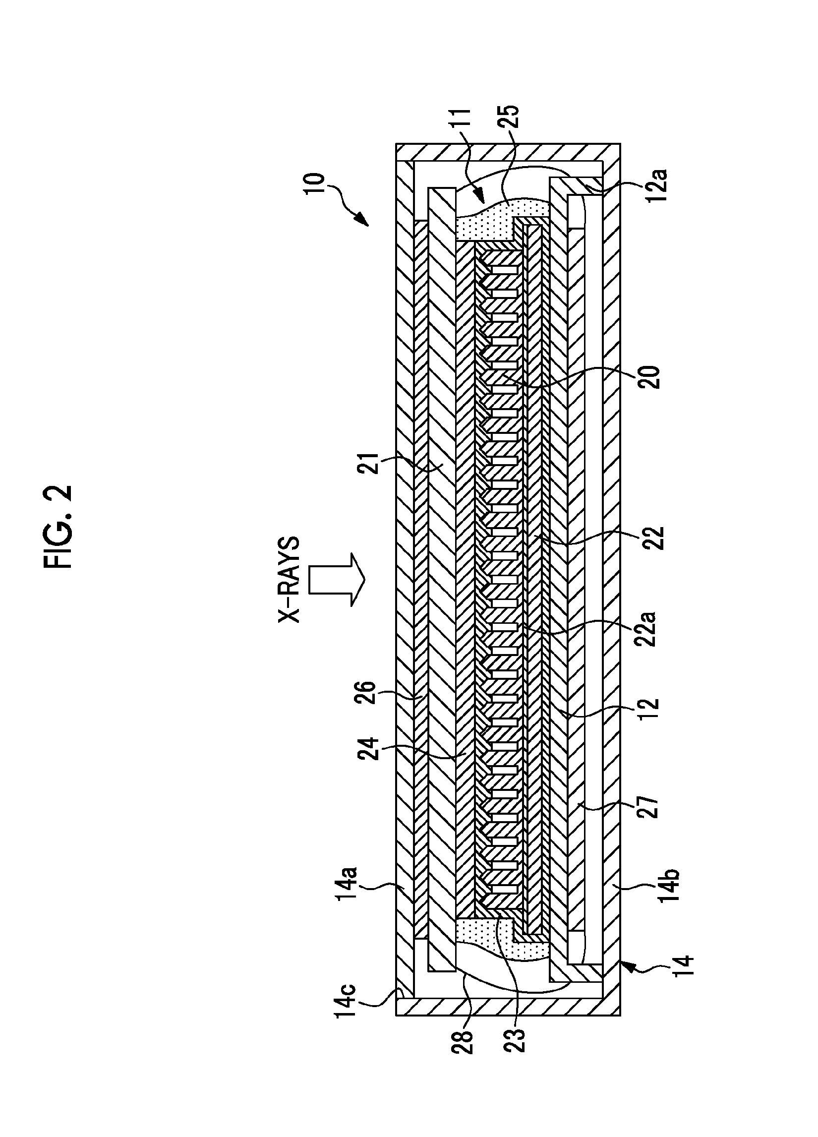
The present invention provides a radiological image detection apparatus with excellent sensitivity. This is achieved by setting the molar ratio of thallium to cesium iodide in the scintillator to be between 0.1 mol % and 0.55 mol % and the half width of the rocking curve of the columnar crystal to be equal to or less than 3°.

Problems solved by technology

Accordingly, since the degree of orientation of crystals with very high orientation cannot be evaluated, there is a problem in that the crystallinity cannot be determined.
In addition, since the sensitivity of the scintillator cannot be sufficiently improved only with a high orientation of crystals, there is a problem in that the sensitivity of the scintillator also depends on the concentration of thallium as an activator.

Method used


Image

  • Radiological image detection apparatus
  • Radiological image detection apparatus
  • Radiological image detection apparatus

Examples


examples

[0059]Hereinafter, the present invention will be specifically described through examples. However, the present invention is not limited to these examples.

first example

1. Formation of a Scintillator

[0060]One of the two crucibles in the vacuum chamber of the vapor deposition apparatus was filled with cesium iodide, and the other one was filled with thallium iodide. An aluminum substrate, which had a thickness of about 300 μm and had a surface on which poly-para-xylene was formed, was prepared as a support substrate, and was set in the vacuum chamber. The degree of vacuum was set to 0.5 Pa by flowing a certain amount of argon gas as process gas after exhausting the vacuum chamber to 5×10⁻³ Pa or less.

[0061]The deposition of the scintillator was started by heating each crucible and rotating the support substrate and opening the shutter of each crucible when the molten state of the material in the crucible was stabilized. In this case, the temperature of each crucible was adjusted so that the Tl / CsI ratio became 0.5 mol %. In addition, the temperature of the support substrate immediately after the start of deposition was set to 40° C. by controlling t...

second example

[0069]An X-ray image detection apparatus of the second example was manufactured under the same conditions as in the first example except that the degree of vacuum of the vacuum chamber of the vapor deposition apparatus was set to 0.4 Pa and the final temperature of the support substrate under deposition was set to 110° C., and measurement and evaluation were performed. As a result, the relative sensitivity was 110, which was acceptable.


PUM


Abstract

There is provided a radiological image detection apparatus having excellent sensitivity. A scintillator has a plurality of columnar crystals formed of thallium-activated cesium iodide, and converts X-rays into visible light and emits the visible light from the distal end of the columnar crystal. A photoelectric conversion panel generates electric charges by detecting the visible light emitted from the scintillator. The molar ratio of thallium to cesium iodide in the scintillator is in a range of 0.1 mol % to 0.55 mol %. The half width of the rocking curve of the (200) plane of the columnar crystal is equal to or less than 3°.

Description

BACKGROUND OF THE INVENTION[0001]1. Field of the Invention[0002]The present invention relates to a radiological image detection apparatus that detects a radiological image.[0003]2. Description of the Related Art[0004]In recent years, in the medical field, a radiological image detection apparatus that detects a radiation (for example, X-rays), which is emitted from a radiation source toward an imaging region of a patient and is transmitted through the imaging region, and converts the radiation into electric charges and generates image data indicating a radiological image of the imaging region based on the electric charges is used to perform diagnostic imaging. There are a direct conversion type radiological image detection apparatus, which directly converts a radiation into electric charges, and an indirect conversion type radiological image detection apparatus, which converts a radiation into visible light first and converts the visible light into electric charges.[0005]The indirect...

Claims


Application Information

Patent Timeline
IPC IPC(8): G01T1/20
CPCG01T1/2006G01T1/202C09K11/628G21K4/00G21K2004/04
Inventor NISHIDA, YOICHINAKAMURA, YUKINORIANZAI, AKIHIRO
Owner FUJIFILM CORP
Learn More