Optical Element and Radiation-Emitting Device Comprising Such an Optical Element

a radiation-emitting device and optical element technology, which is applied in the direction of semiconductor devices for light sources, lighting and heating apparatus, instruments, etc., can solve the problems of large losses, non-homogeneous illumination, and reduced efficiency

Active Publication Date: 2014-01-02
OSRAM OLED
View PDF11 Cites 30 Cited by
  • Summary
  • Abstract
  • Description
  • Claims
  • Application Information

AI Technical Summary

Benefits of technology

[0006]In one aspect, the present application provides an optical element which avoids the above-stated disadvantages, whereby an optical element is advantageously obtained which enables homogeneous illumination. In a further aspect, the present application provides a radiation-emitting device having such an optical element, in which the device is distinguished by particularly homogeneous emission efficiency across the emission angle.
[0010]Very high emission efficiency can be achieved with such an optical element as substantially only Fresnel losses occur. In addition, the problem of light mixing and of shadows being cast is simultaneously solved. Any further optical systems optionally arranged downstream may here be of substantially simpler design. Moreover, the microstructures may be configured such that they are already suitable for radiation shaping.
[0033]A device having such an optical element is distinguished in particular by a homogeneous emission pattern of the emitted radiation. This gives rise to very high emission efficiency, since substantially only Fresnel losses occur. At the same time, optimum mixing of the radiation emitted by the component is ensured, wherein shadows are not cast. The refractive microstructures may here be designed such that they assist in shaping the radiation emitted by the component.
[0036]The optical element of the device advantageously cancels out the spatial separation of the individual semiconductor components, whereby the emission pattern may advantageously be homogenized.
[0038]By purposeful selection of the semiconductor components, it is possible to produce a device which emits radiation from a specific color coordinate range, for example, a white-emitting device.

Problems solved by technology

The disadvantageous consequence is non-homogeneous illumination.
Disadvantageously, however, this results in large losses, since a large proportion of the light emitted by the LED is scattered back in a backwards direction and is thus for the most part lost to the intended application.
However, this is likewise disadvantageous since this method is based on shading the emitted beam of light, so reducing efficiency.
Moreover, this method does only solve the problem of shadows being cast.
In addition, elevated assembly costs are involved.

Method used


Image

  • Optical Element and Radiation-Emitting Device Comprising Such an Optical Element
  • Optical Element and Radiation-Emitting Device Comprising Such an Optical Element
  • Optical Element and Radiation-Emitting Device Comprising Such an Optical Element

Examples


Embodiment Construction

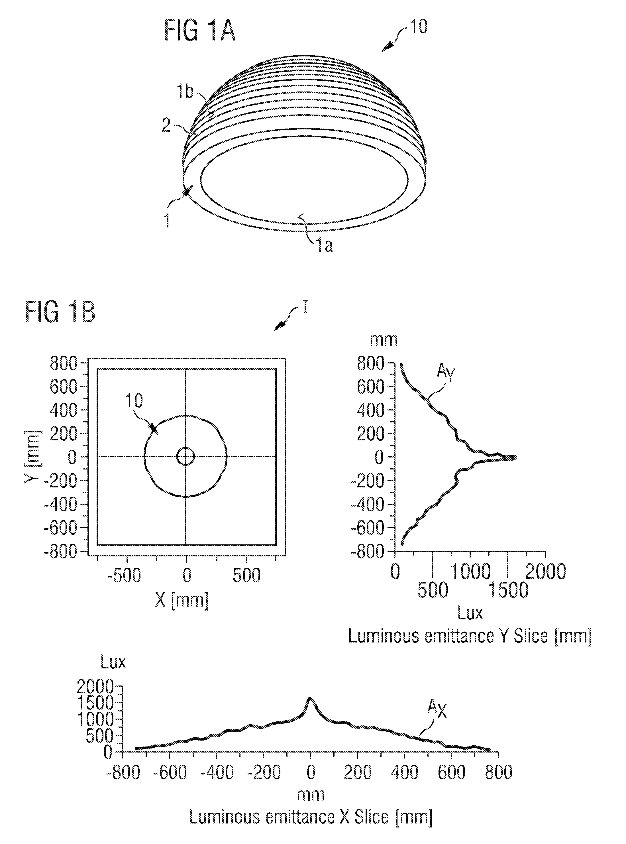
[0050]FIG. 6A is a cross-section of a radiation-emitting device according to the prior art which comprises semiconductor components 3 which are arranged in a reflector 4. The semiconductor components 3 emit radiation when in operation, at least some of which is reflected on the reflector 4. Due to shading of the light emission at the opening of the reflector 4, shadows are here disadvantageously cast. Moreover, the beam of light may be split in accordance with the symmetry of the component arrangement.

[0051]It is known from the prior art to solve these problems by means of diffusers, which are, for example, arranged above the components (not shown). A disadvantage here, however, is that such arrangements cause major losses. It is alternatively known to improve the aperture of a secondary optical system downstream of the reflector by mounting three-dimensional structures, for example, teeth or films with transmission gradients (not shown). The high cost of mounting such teeth or film...


PUM


Abstract

An optical element has an optical body and a number of microstructures. The optical body takes the form of a half-shell and has an inner face and an outer face. The microstructures form the inner and / or outer face of the optical body at least in places and are light-scattering refractive structures. The invention further relates to a radiation-emitting device having at least one semiconductor component and one such optical element.

Description

[0001]This patent application is a national phase filing under section 371 of PCT / EP2012 / 051378, filed Jan. 27, 2012, which claims the priority of German patent application 10 2011 015 405.1, filed Mar. 29, 2011, each of which is incorporated herein by reference in its entirety.TECHNICAL FIELD[0002]The invention relates to an optical element comprising an optical body and a plurality of microstructures and to a radiation-emitting device having a semiconductor component and such an optical element.BACKGROUND[0003]If radiation-emitting devices of high brightness are to be produced, it is necessary to use more than one radiation-emitting component in order to achieve the required brightness. One option in these applications is, for example, to use an arrangement of a plurality of LEDs mounted side by side. If an optical system is used to shape the light emitted by the LEDs, one consequence of using the plurality of LEDs spatially separated from one another is inter alia that the focuse...

Claims


Application Information

Patent Timeline
Patent Type & Authority Applications(United States)
IPC IPC(8): G02B3/00
CPCG02B3/0006F21V5/002F21V5/045F21Y2105/10F21Y2115/10G02B3/08F21V5/005
Inventor STREPPEL, ULRICHMARKYTAN, ALESGAERTNER, CHRISTIAN
Owner OSRAM OLED
Why Eureka
Try Eureka