Eureka AIR delivers breakthrough ideas for toughest innovation challenges, trusted by R&D personnel around the world.

Motor

Inactive Publication Date: 2014-01-02
LG INNOTEK CO LTD
View PDF8 Cites 3 Cited by
  • Summary
  • Abstract
  • Description
  • Claims
  • Application Information

AI Technical Summary

Benefits of technology

The present invention aims to provide a motor that is cost-effective and reliable over a long period of use. It achieves this by improving the structure of the pulley, which increases belt reliability. This is achieved by using a metal rod material to cut a groove between a flange and a pulley gear part, which then forms the surface of the pulley gear through roll forming. This method reduces manufacturing costs and enhances the life of the motor's belt.

Problems solved by technology

However, in a case the power transmission unit is formed by a belt pulley system, there may occur an error in the manufacturing process such as burrs and / or edges at a connection portion where a flange member provided at the pulley to inhibit the belt from being disengaged and a gear surface formed on a pulley surface, and if the error occurs, a problem may be generated in that belt portion contacting the burrs or edges easily wears.
Another problem is that, in a case the pulley is manufactured using a sintering process, in view of the fact that the pulley is largely manufactured through the sintering process using a metal mold in consideration of durability, the manufacturing cost may increase due to excessively high cost of mold manufacturing, and if a mold is used more than a predetermined number of times, accuracy of the sintered pulley may deteriorate.

Method used


Image

  • Motor
  • Motor
  • Motor

Examples


Embodiment Construction

[0032]Now, a motor according to the exemplary embodiment of the present disclosure will be described in detail with reference to the accompanying drawings.

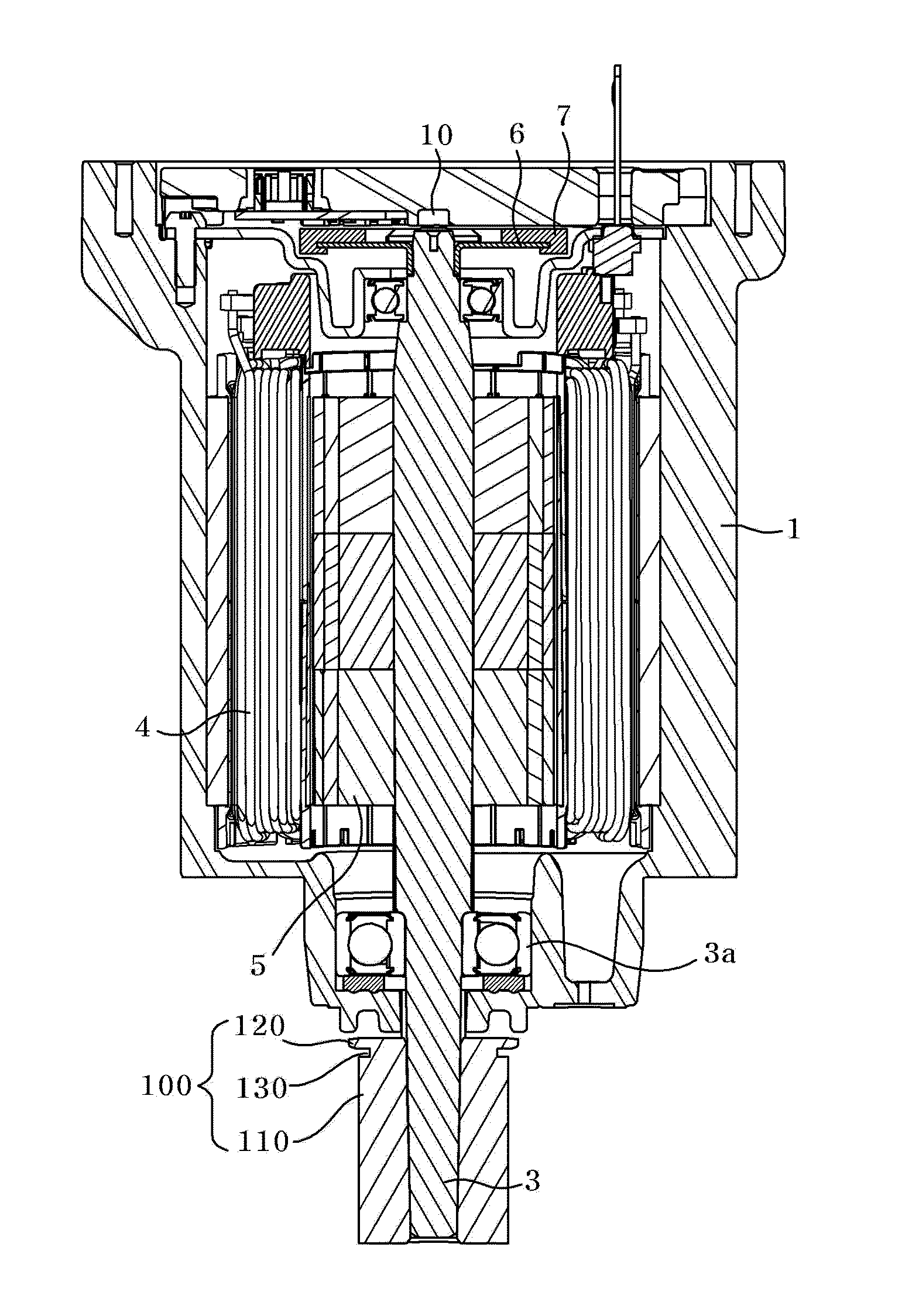
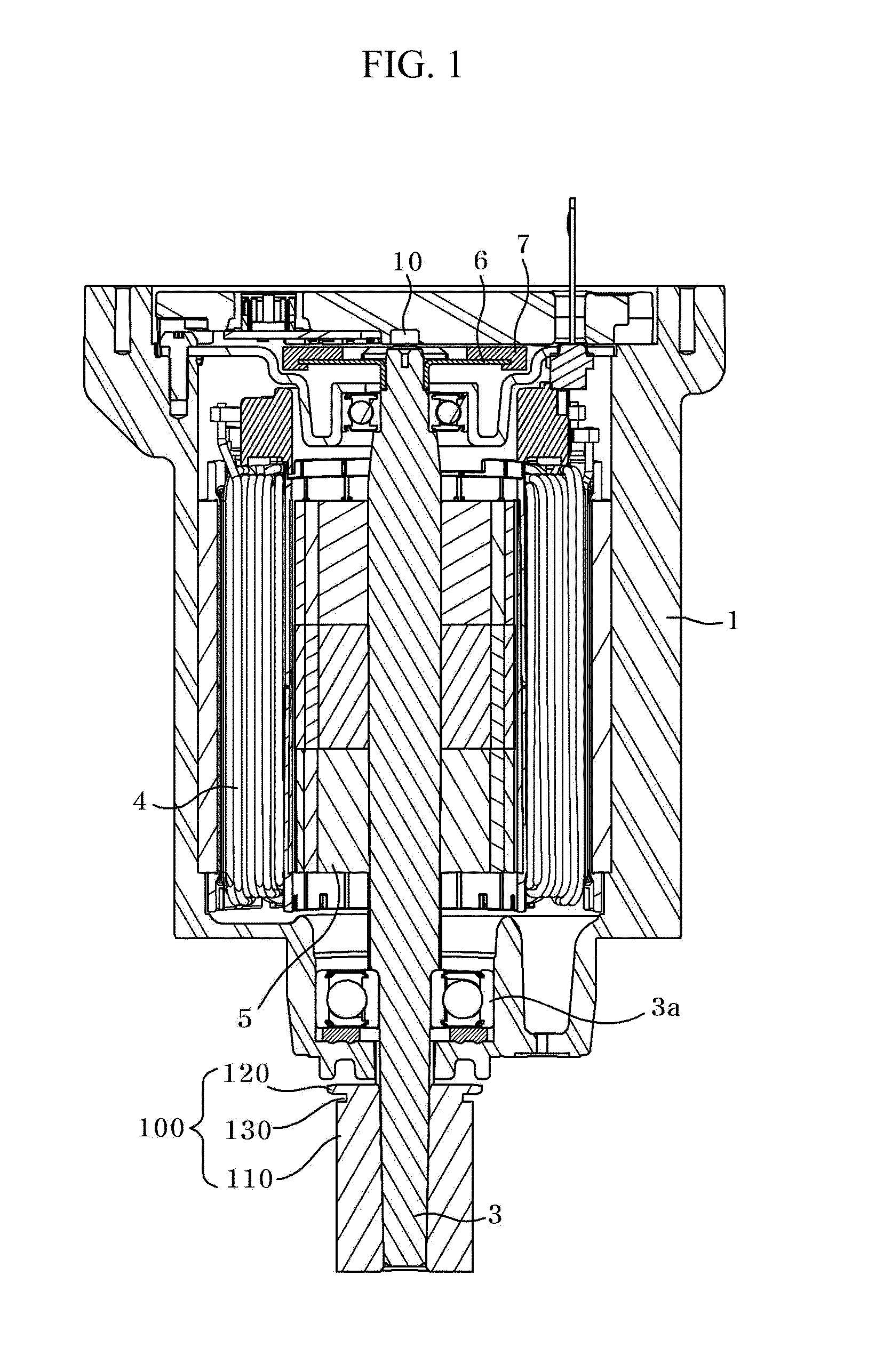
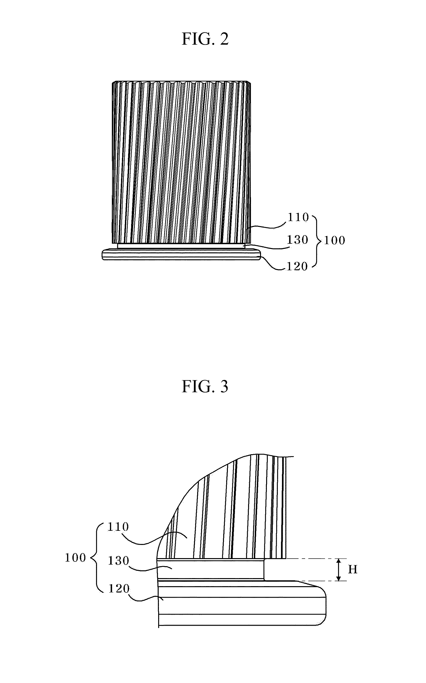
[0033]FIG. 1 is a schematic cross-sectional view illustrating an EPS motor according to an exemplary embodiment of the present disclosure, FIG. 2 is schematic view illustrating an EPS motor according to an exemplary embodiment of the present disclosure, and FIG. 3 is an enlarged view of a flange of a pulley illustrated in FIG. 2.

[0034]Referring to FIG. 1, an EPS motor according to an exemplary embodiment of the present disclosure includes a housing (1) and a cover member (not shown) coupled to an upper surface of the housing (1), and an external look of the motor is constituted by combination of the housing (1) and the cover member.

[0035]A fixing bracket is provided at a lateral surface of the housing (10), a stator (4) wound with a plurality of coils is provided at an inner surface of the housing (1) and a rotor (5) is rotatably ...


PUM


Abstract

A motor is provided, the motor including a housing, a stator mounted inside the housing, a rotor rotatably installed at a center of the stator by a rotation shaft, and a pulley rotating in association with the rotation shaft, wherein the pulley includes a belt gear coupled by a belt at a periphery, a flange formed at one side of the belt gear to have a diameter greater than that of the belt gear, and a relief groove formed between the belt gear and the flange to distance the belt gear from the flange.

Description

CROSS-REFERENCE TO RELATED APPLICATION[0001]This application claims the benefit under 35 U.S.C. §119 of Korean Application No. 10-2012-0069851, filed Jun. 28, 2012, which is hereby incorporated by reference in its entirety.BACKGROUND[0002]1. Field of the Disclosure[0003]The present disclosure relates to a brushless motor.[0004]2. Discussion of the Related Art[0005]Generally, almost every vehicle employs an electric power-assist steering system. Such an electric power-assist steering system generates an assist force based on the steering torque and the steering angle in order to enhance the steering performance of the vehicle.[0006]That is, a steering system that assists a steering force of a vehicle with a separate power is used to enhance the motion stability of a vehicle.[0007]Conventionally, the auxiliary steering device uses hydraulic pressure, but an Electronic Power Steering (EPS) system adapted to transmit a rotation output of an electric motor to a steering shaft via a speed...

Claims


Application Information

Patent Timeline
IPC IPC(8): H02K7/10H02K7/116
CPCH02K7/1008H02K7/116H02K7/10H02K29/00
Inventor CHANG, DONG, GEUN
Owner LG INNOTEK CO LTD
Why Eureka
Eureka Blog
Learn More