Eureka AIR delivers breakthrough ideas for toughest innovation challenges, trusted by R&D personnel around the world.

System for simultaneous dual-slab acquisition of mr images

a dual-slab, mr imaging technology, applied in the direction of nmr measurement, diagnostic recording/measuring, instruments, etc., can solve the problems of individual slabs and significant differences in image contrast between the two slices/slabs, so as to reduce the difference in te between the two slabs, maximize the effect of te difference, and reduce the difference in

Active Publication Date: 2014-01-02
SIEMENS HEALTHCARE GMBH
View PDF18 Cites 17 Cited by
  • Summary
  • Abstract
  • Description
  • Claims
  • Application Information

AI Technical Summary

Benefits of technology

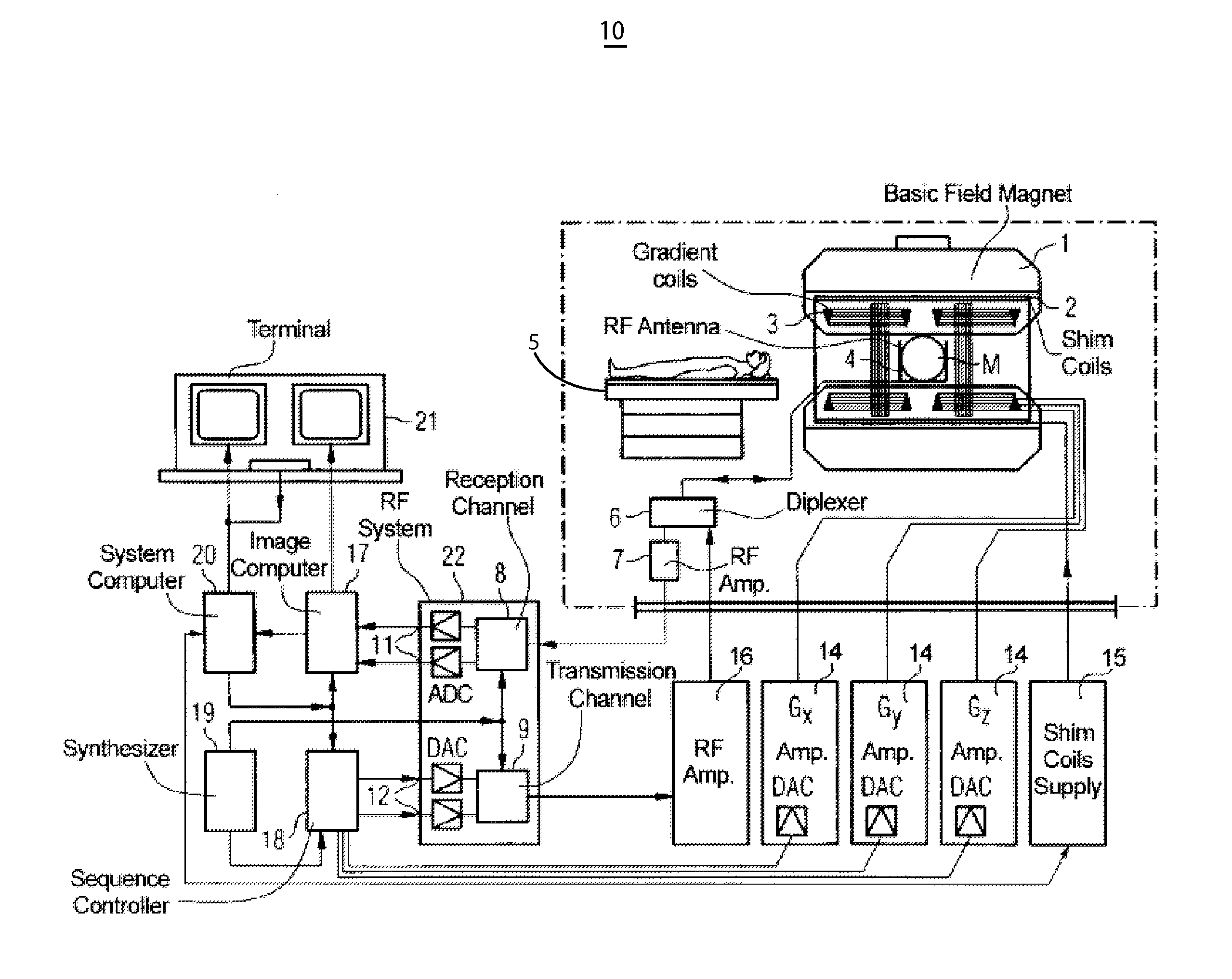
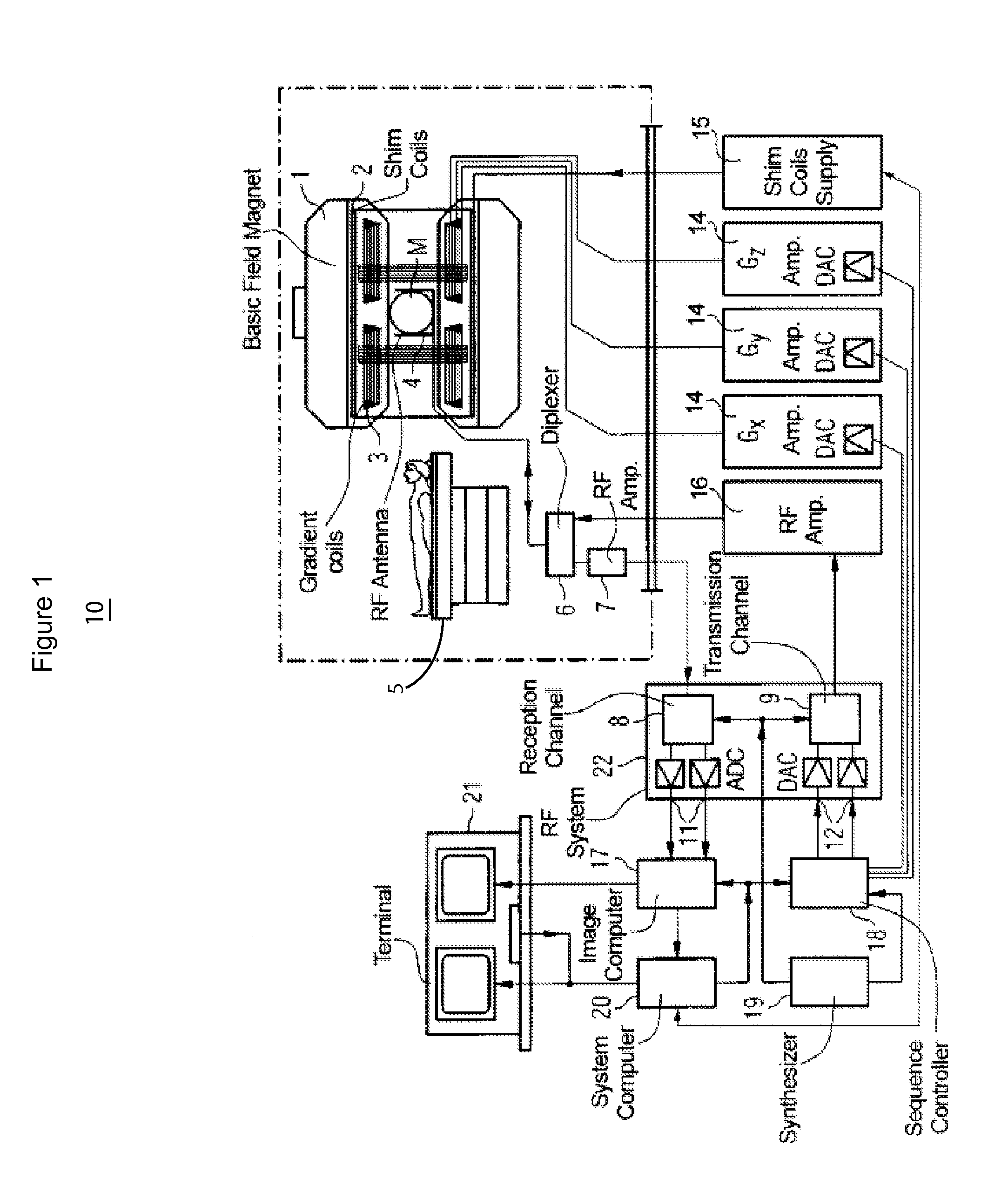
The invention describes a system for magnetic resonance imaging (MRI) that uses two different RF pulses to excite different slabs of tissue. One RF pulse is applied first and is asymmetric, meaning it is designed to late traverse the center of k-space. The second RF pulse is reversed asymmetric, meaning it is designed to early traverse the center of k-space. By combining these two RF pulses, the system can achieve a dual-slab acquisition, reducing the difference in the MRI signal between the two slabs and improving the quality of the resulting images. This technology can be used in breast and peripheral MRI angiography imaging, for example. The system uses multiple RF coils and a magnetic field gradient generator to acquire data from different anatomical regions simultaneously, improving the speed and accuracy of MRI scans.

Problems solved by technology

One limitation of dual (or multi) band pulses is that the individual slabs need to be the same thickness and orientation, but only spatially separated.
Since TE has a large impact on the soft tissue contrast, this difference in TE can create a significant difference in image contrast between the two slices / slabs, which is undesirable.

Method used


Image

  • System for simultaneous dual-slab acquisition of mr images
  • System for simultaneous dual-slab acquisition of mr images
  • System for simultaneous dual-slab acquisition of mr images

Examples


Embodiment Construction

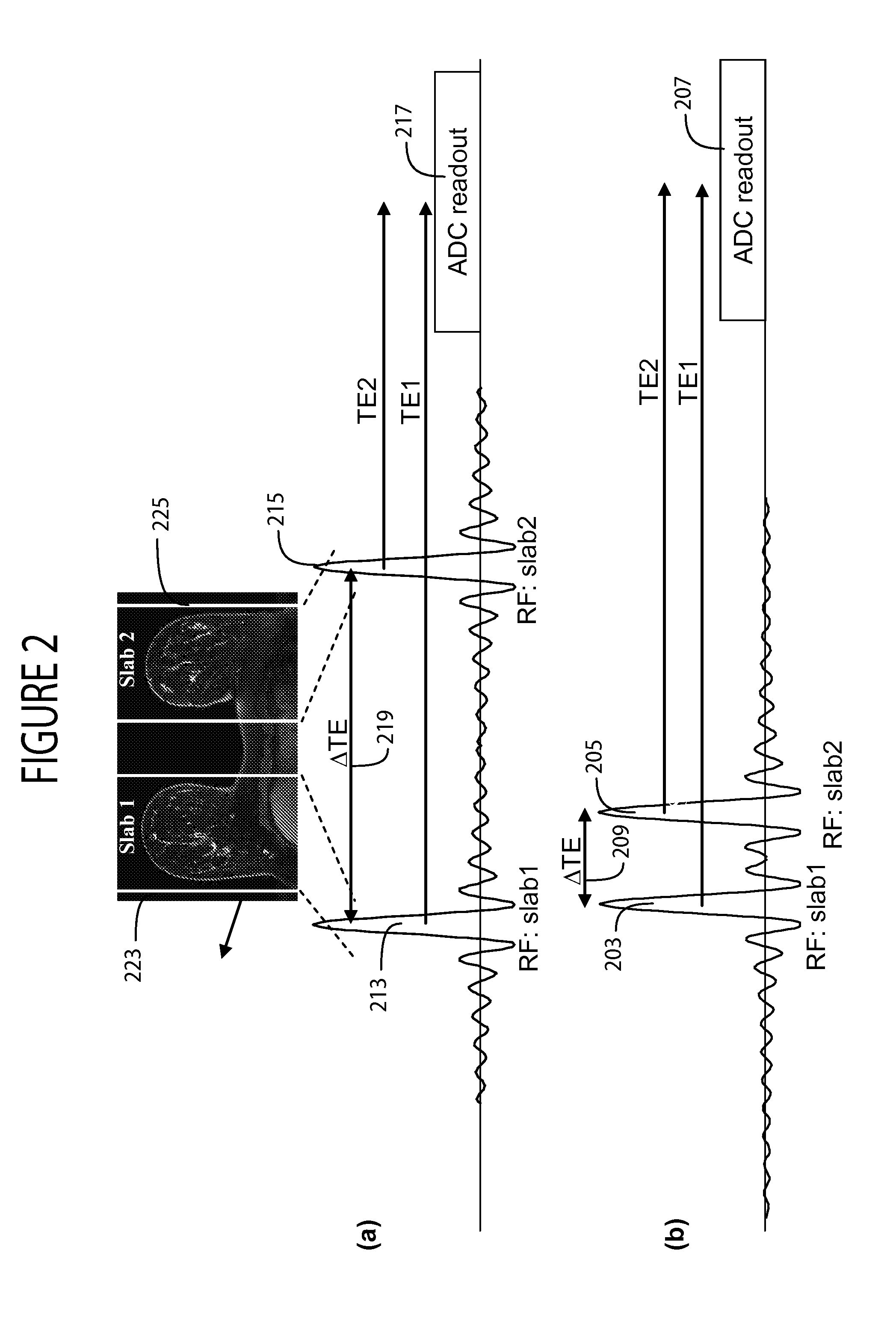
[0011]A system in one embodiment, uses two concatenated separate RF pulses for wideband MRI advantageously reducing difference in echo time (TE) and image luminance contrast in dual slab imaging of left and right breasts, for example. FIG. 2(b) shows two concatenated separate RF pulses 203, 205 with corresponding echo time (TE1 and TE2) having reduced difference ATE 209 and used for acquisition of two slabs (e.g. of left and right breasts). The sequence of RF pulses 203, 205 advantageously comprises an asymmetric pulse 203 concatenated with a reversed asymmetric pulse 205 having respective echo times TE1, TE2 between the start of RF pulses 203, 205 to a maximum in the received echo signal during readout 207. In contrast, FIG. 2(a) shows a known two symmetric RF pulse sequence including RF pulses 213, 215 with corresponding echo time (TE1 and TE2) between the start of RF pulses 213, 215 to a maximum in the received echo signal during readout 217 and having difference ΔTE 219 substant...


PUM


Abstract

A system uses multiple RF coils in MR imaging and an RF (Radio Frequency) signal generator generates RF excitation pulses in anatomical regions of interest and enables subsequent acquisition of associated RF echo data. A magnetic field gradient generator generates anatomical volume select magnetic field gradients for phase encoding and readout RF data acquisition. The RF signal generator and the gradient generator substantially concurrently acquire first and second volumes of first and second different anatomical regions by providing, a first RF pulse having a first asymmetric shape followed by a successive second RF pulse substantially having the first asymmetric shape but reversed in time, to substantially reduce echo time (TE) differences between acquisition of the first and second volumes and a phase encoding magnetic field gradient prepares for acquisition of data representing the first and second volumes.

Description

CROSS-REFERENCE TO RELATED APPLICATIONS[0001]This application is a non-provisional of, and claims priority to, U.S. provisional patent application Ser. No. 61 / 664,869 by V. S. Deshpande et al. filed on Jun. 27, 2012.FIELD OF THE INVENTION[0002]This invention concerns a system for using multiple RF coils in MR imaging of an anatomical volume of breast or other anatomy, by concurrently acquiring first and second volumes of first and second different anatomical regions using an RF pulse sequence to substantially reduce echo time (TE) differences between the first and the second volume which are acquired concurrently.BACKGROUND OF THE INVENTION[0003]Imaging speed can be doubled as known with minimal loss in signal-to noise-ratio (SNR) by using a multi band acquisition. For a dual-band example, this is achieved by exciting two spatially separated slabs concurrently using a wideband pulse, and concurrently reading out the data. Concurrent readout of the two slabs leads to image aliasing, ...

Claims


Application Information

Patent Timeline
Patent Type & Authority Applications(United States)
IPC IPC(8): G01R33/56G01R33/36
CPCG01R33/56G01R33/3628G01R33/4835G01R33/561A61B5/055
Inventor DESHPANDE, VIBHAS S.LAUB, GERHARD
Owner SIEMENS HEALTHCARE GMBH
Why Eureka
Eureka Blog
Learn More