Method for Fitting Motor Vehicle Suspension Systems

a suspension system and motor vehicle technology, applied in the field of assembling motor vehicles, can solve the problems of large space requirement in the assembly hangar, high investment cost, and large expenditure on conveyance and transportation technology

Active Publication Date: 2014-01-09
DAIMLER AG
View PDF12 Cites 12 Cited by
  • Summary
  • Abstract
  • Description
  • Claims
  • Application Information

AI Technical Summary

Benefits of technology

[0010]Since the shell has to be guided through the main assembly line by means of corresponding conveyance and transportation technology for the equipment with the interior installation, and the chassis and the drive train have to be guided through their respective pre-assemblies, a considerable amount of expenditure for conveyance and transportation technology arises overall for the assembly of the motor vehicle. This entails not only high investment costs, but also a large space requirement in the assembly hangars. Furthermore, assembly with the existing conveyance and transportation technology is relatively inflexible.
[0011]Exemplary embodiments of the present invention are directed to a method for the assembly of motor vehicles of the type cited above, by means of which the expenditure for conveyance and transportation technology is considerably reduced.
[0013]In other words, provision is thus made according to the invention for the motor vehicle to have vehicle wheels added to it at a far earlier point than has been typical to-date (which is typically after the main assembly line), in order to thus save at least one part of the conveyance and transportation technology, which is necessary for taking the weight of the motor vehicle and, if necessary, for moving the motor vehicle along. Since the motor vehicle can bear its own weight after the assembly of the vehicle wheels and at least roll, it is at least no longer necessary for the main assembly line to take the weight of the motor vehicle in the further procedure. This not only enables a considerable saving in conveyance and transportation technology with the consequential effects linked thereto, but a far more flexible assembly is also achieved. It is thus possible, for example, to carry out an offtake buffering of motor vehicles in a very flexible manner at an early point in time, and, if necessary, to store this temporarily before the further assembly is to take place. To that end, only one corresponding storage area is required.
[0017]Finally, it has been shown to be advantageous if the movement of the motor vehicle onto the vehicle wheels takes place via a control device of the assembly line, in particular the main assembly line. Thus, the motor vehicle can be adjusted to the flow of the assembly line via external control signals.

Problems solved by technology

Since the shell has to be guided through the main assembly line by means of corresponding conveyance and transportation technology for the equipment with the interior installation, and the chassis and the drive train have to be guided through their respective pre-assemblies, a considerable amount of expenditure for conveyance and transportation technology arises overall for the assembly of the motor vehicle.
This entails not only high investment costs, but also a large space requirement in the assembly hangars.
Furthermore, assembly with the existing conveyance and transportation technology is relatively inflexible.

Method used


Image

  • Method for Fitting Motor Vehicle Suspension Systems
  • Method for Fitting Motor Vehicle Suspension Systems
  • Method for Fitting Motor Vehicle Suspension Systems

Examples


Embodiment Construction

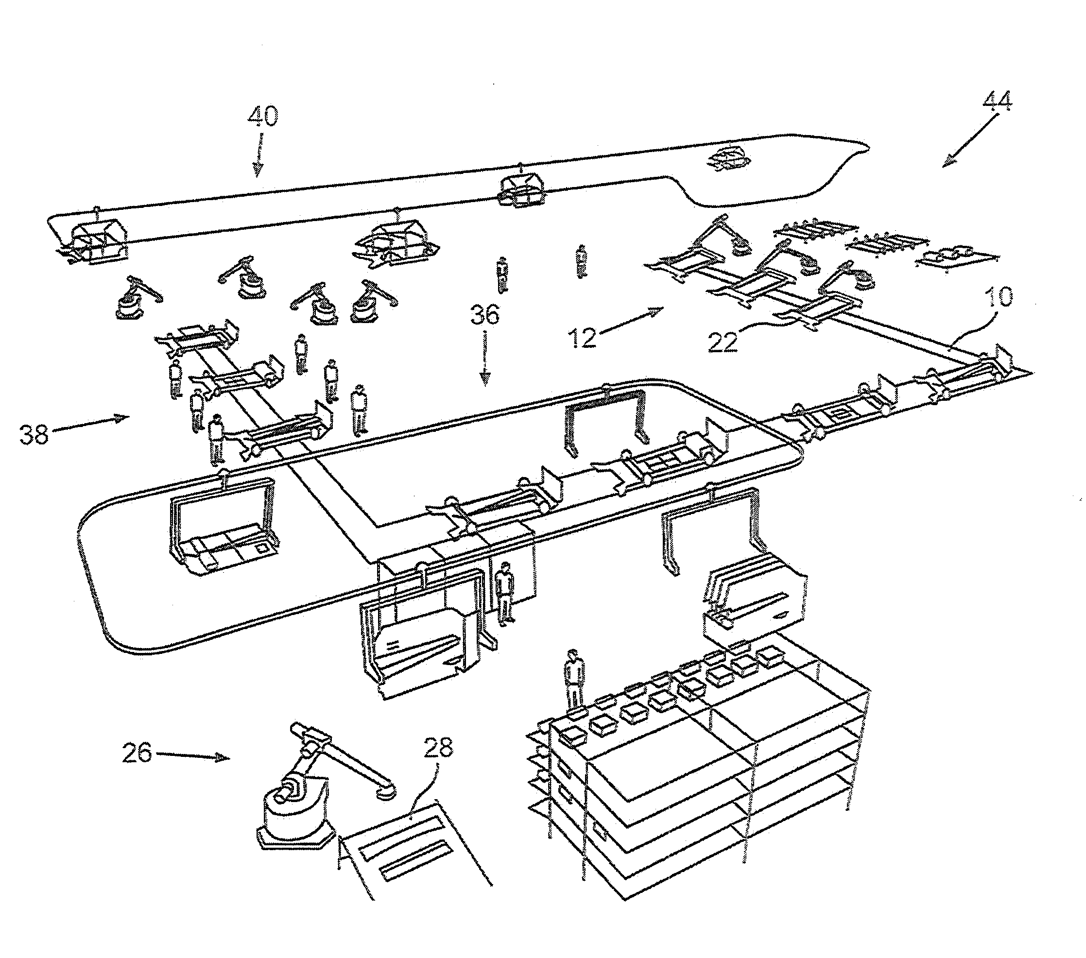
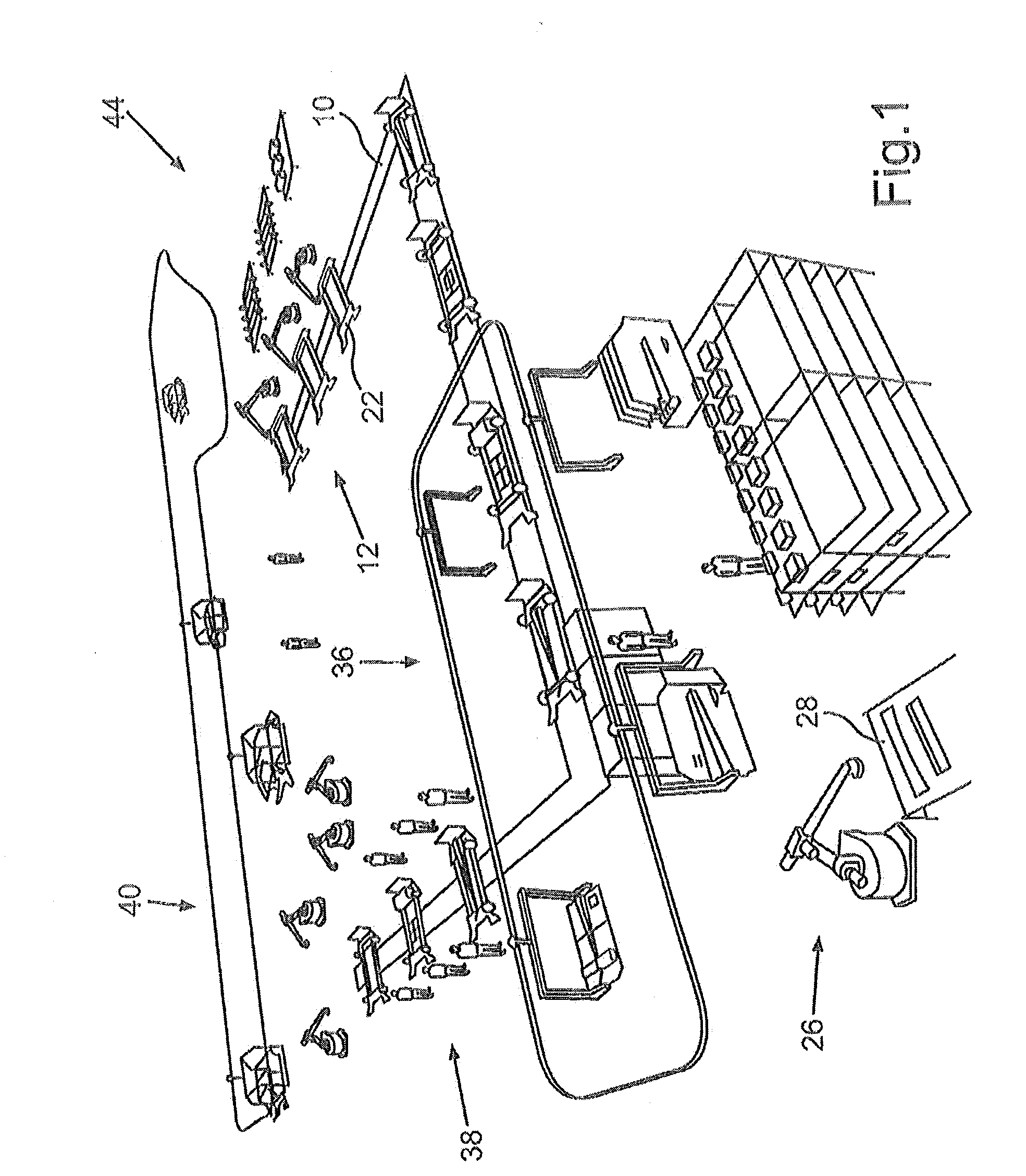
[0028]FIG. 1 depicts, in a schematic perspective view, an assembly line arranged upstream of a main assembly line (to be illustrated in greater detail) for the assembly of motor vehicles. This assembly line 10 is to be furthermore illustrated in detail in conjunction with FIGS. 2 to 6.

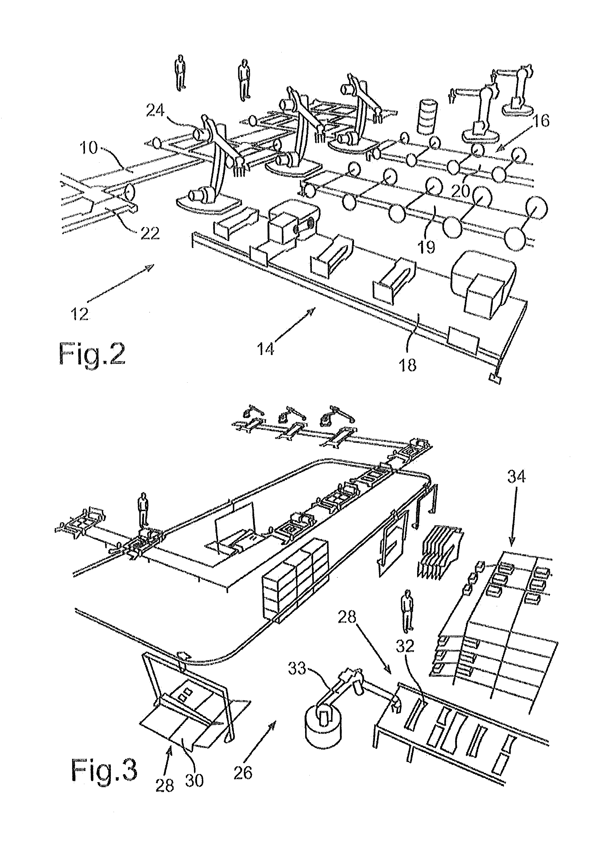
[0029]First, in conjunction with FIG. 2, a first region 12 of the assembly line 10 can be seen, which shows the pre-assembly of a respective drive train 14 and a respective chassis 16 of the corresponding motor vehicle. Here, FIG. 2 shows the region 12 in a schematic and sectional perspective view.

[0030]As can be seen from FIG. 2, the region 12 of the assembly line 10 comprises a supply device 18 for a respective different drive or drive train 14, which is provided depending on the respective drive concept of the motor vehicle. Respective supply devices 19, 20 for a front axle or rear axle of the respective chassis 16 can be seen behind the supply device 18 for the respective drive or drive train 14. M...


PUM

PropertyMeasurementUnit
movementaaaaaaaaaa
weightaaaaaaaaaa
flexibleaaaaaaaaaa

Abstract

A method for assembling motor vehicles, in particular personal motor vehicles having a self-supporting shell involves equipping the respective shell of the motor vehicle with a corresponding chassis and equipping the chassis with vehicle wheels at least before an end of a main assembly line has been reached.

Description

BACKGROUND AND SUMMARY OF THE INVENTION[0001]Exemplary embodiments of the present invention relate to a method for assembling motor vehicles.[0002]It is commonly known from the series production of vehicles, in connection with the shell production and the subsequent coating of the respective shell bodies, to equip these with a respective interior installation in a main assembly line of the final assembly. Here, the bodies are guided through the main assembly line by means of corresponding conveyance and transportation technology. In this instance, the dashboard, the seating units, the central console, the pedals, the steering column and the interior trim, for example, are assembled as large modules. In parallel with the final assembly of the interior installation, a pre-assembly of the chassis and drive train typically takes place in the main assembly line, wherein these components are typically assembled and transported on a separate conveyance means. After the respective shell of ...

Claims


Application Information

Patent Timeline
Patent Type & Authority Applications(United States)
IPC IPC(8): B62D65/12
CPCB62D65/12Y10T29/49622B23P23/06B62D65/02
Inventor GREVENER, CHRISTOPHHABISREITINGER, UEWKREVET, ANDREASMUELLER, MATTHIASSTARK, THOMASWIRTH, KONRADZUERN, MICHAEL
Owner DAIMLER AG
Why Eureka
Try Eureka