Wireless power transmission system, power transmitting device, and power receiving device

a power transmission system and wireless technology, applied in the direction of electric devices, charging stations, transportation and packaging, etc., can solve the problems of resonant magnetic field leakage out of the system, low coupling efficiency, and harm to surrounding persons, and achieve the effect of minimizing such a leakage magnetic field

Inactive Publication Date: 2014-01-09
SOVEREIGN PEAK VENTURES LLC
View PDF3 Cites 46 Cited by
  • Summary
  • Abstract
  • Description
  • Claims
  • Application Information

AI Technical Summary

Benefits of technology

[0007]There is concern that when electric power is transmitted via resonant magnetic coupling, the resonant magnetic field might leak out of the system and could do harm on surrounding persons. An embodiment of the present invention provides a wireless power transmission system and power transmitting device that can minimize such a leaking magnetic field.

Problems solved by technology

Such a wireless power transmission system can raise the voltage effectively in transmitting electric power with relatively low coupling efficiency.
There is concern that when electric power is transmitted via resonant magnetic coupling, the resonant magnetic field might leak out of the system and could do harm on surrounding persons.

Method used


Image

  • Wireless power transmission system, power transmitting device, and power receiving device
  • Wireless power transmission system, power transmitting device, and power receiving device
  • Wireless power transmission system, power transmitting device, and power receiving device

Examples


embodiments

[0052]Hereinafter, embodiments of a wireless power transmission system according to the present invention will be described with reference to the accompanying drawings.

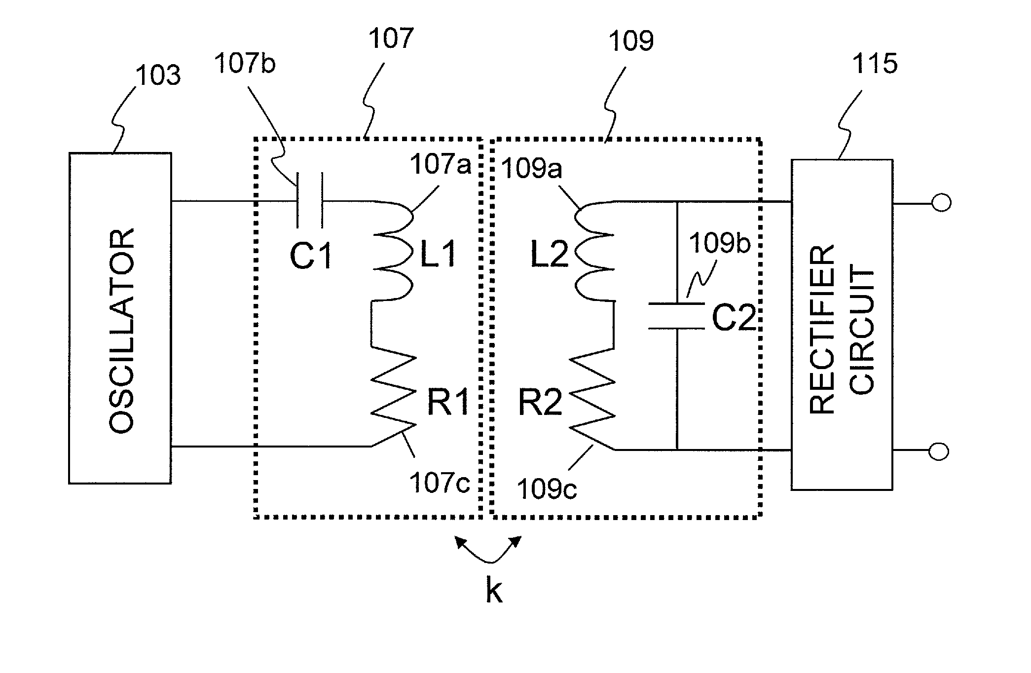
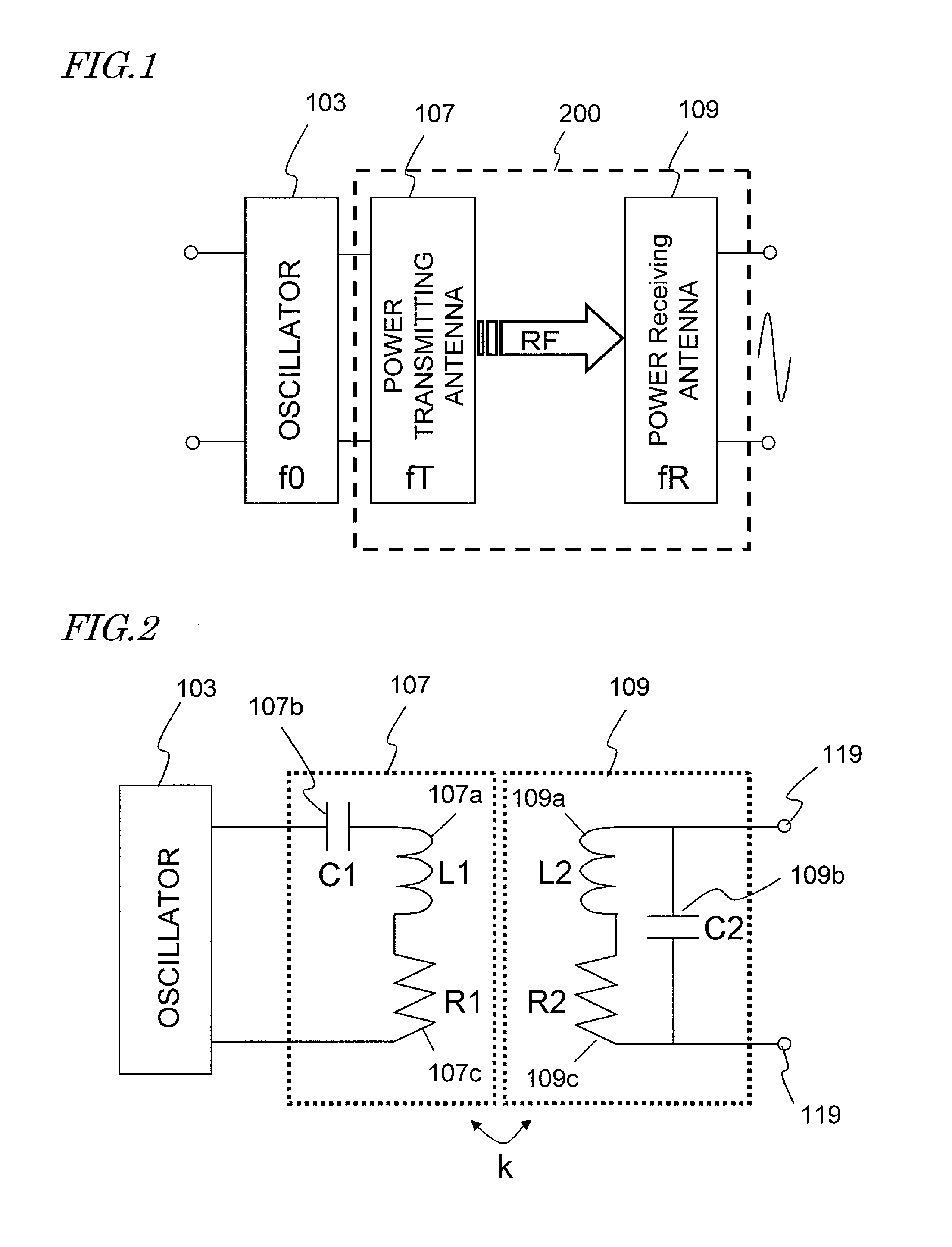
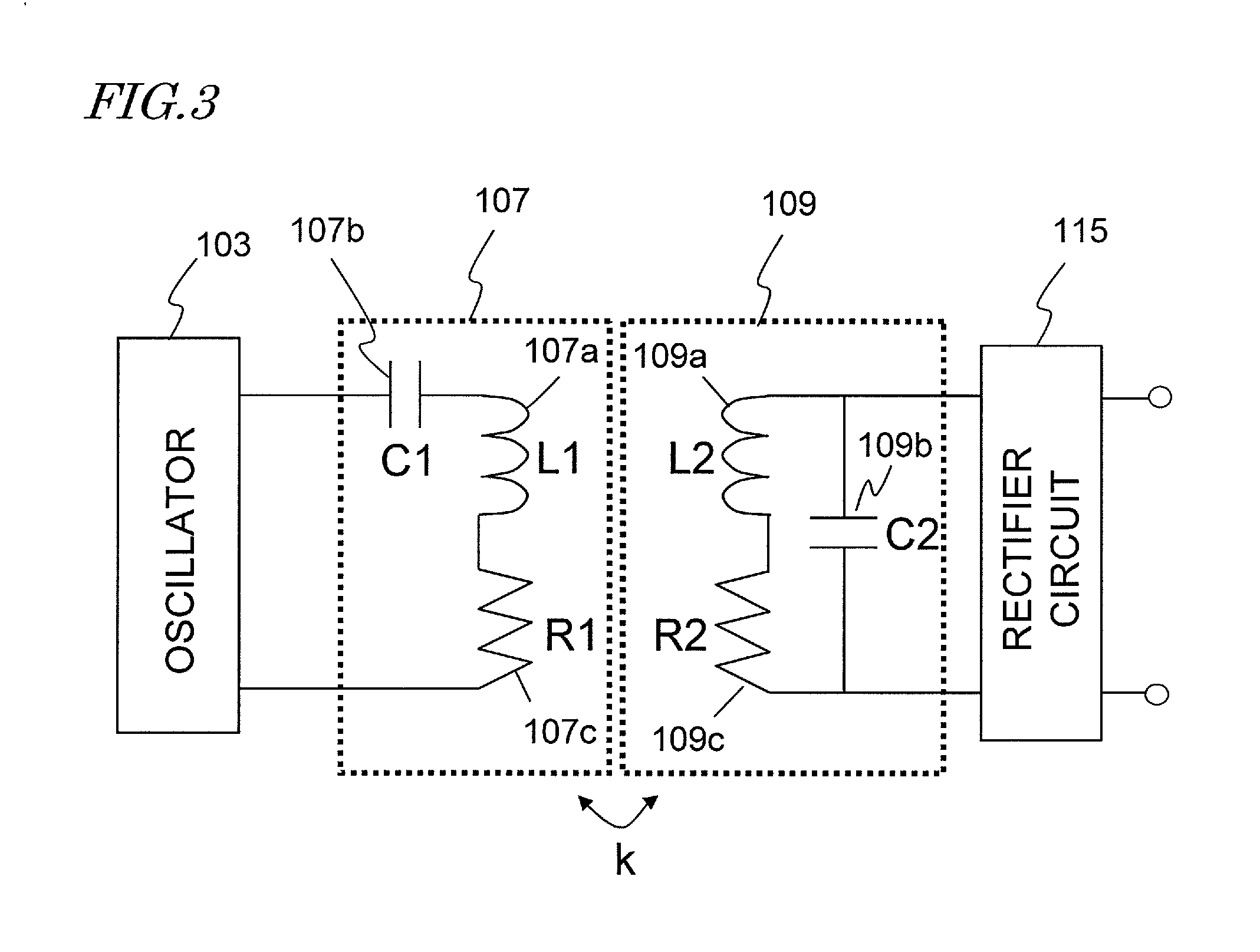
[0053]First of all, look at FIGS. 4 and 5, which are respectively is a perspective view and a side view schematically illustrating the arrangement of antennas in a wireless power transmission system according to an embodiment. In FIGS. 4 and 5, of those components of the wireless power transmission system of the present disclosure described above, only the first and second inductors 107a and 109a are shown for the sake of simplicity. The first and second inductors 107a and 109a are actually connected to the circuit elements shown in FIG. 2 through cables (not shown). In the following description, the first and second inductors 107a and 109a will be sometimes referred to herein as the power transmitting antenna 107 and the power receiving antenna 109, respectively, for the sake of simplicity.

[0054]As shown in FIG. 4, e...

example 1

[0079]As to a specific example having numerical parameters shown in the following Table 2, the distribution of the magnetic field strengths in the space was obtained by analyzing the electromagnetic field. A structure defined by those numerical parameters is as shown in FIG. 12. Meanwhile, as a comparative example, a system having the same configuration as that specific example, except that the protruding portion 200c was removed, was made and the distribution of leaking magnetic field strengths was obtained by simulations. In this specific example, the antennas 107 and 109 and the electromagnetic shield structure 200 are supposed to be axisymmetric with respect to the Z axis for the sake of simplicity:

TABLE 2G05.0 cmG15.0 cmG25.0 cmG33.0 cmG43.0 cmG5  5 cmEL3.0 cm

[0080]In this example, each of the inductors 107a and 109a had a circular shape with a radius of 7.5 cm, the number of turns of 11, and a capacitance of 33000 pF. The power transmitted wirelessly was set to be 3 kW (at a t...

example 2

[0083]FIG. 14 is a graph showing how the leaking magnetic field strength changed with the length EL of the protruding portion 200c in Example 1 described above. In FIG. 14, the ordinate represents the ratio of magnetic field strength suppression to the value obtained when no protruding portions 200c were provided, and the abscissa represents the length EL of the protruding portion 200c introduced. In FIG. 14, shown is the magnetic field strength suppression ratio that was measured at a point where (X, Y, Z)=(7.5 cm+G3+EL, 0, 0). The size of the protruding portion 200c other than the length EL has its data indicated by the dotted line graph if its value is equal to the parameter value of the first example. On the other hand, the data of the parameter value in the first example that was obtained when G1=G2=0.5 cm is indicated by the solid line graph. In this specific example, the transmission power was set to be 200 W and the transmission frequency was set to be 750 kHz.

[0084]As can b...


PUM


Abstract

This wireless power transmission system includes: a power transmitting antenna and a power receiving antenna arranged to face each other and not to be in contact with each other; and an electromagnetic shield structure that includes a first shield and a second shield to house, in its inner space, the power transmitting and power receiving antennas facing each other. The first and second shields are configured to make first and second spaces to house the power transmitting and power receiving antennas, respectively. At least one of the first and second shields includes a protruding portion that is parallel to at least one of the power transmitting and power receiving antennas and that protrudes out of the shield sidewalls. Power is transmitted by a non-contact method through a radio frequency magnetic field from the power transmitting antenna to the power receiving antenna.

Description

[0001]This application claims priority under 35 USC §119(e) to U.S. Provisional Application No. 61 / 668,198 filed on Jul. 5, 2012, the entire contents of which are incorporated herein by reference.BACKGROUND[0002]1. Technical Field[0003]The present disclosure relates to a resonant magnetic coupling type non-contact power transmission technology for transmitting power wirelessly by using resonant magnetic coupling.[0004]2. Description of the Related Art[0005]United States Patent Application Publication No. 2008 / 0278264 (FIGS. 10 and 12) discloses a new type of wireless power transmission system for transmitting power through a space from one of two resonators to the other, and vice versa. That wireless power transmission system couples those two resonators with each other via the evanescent tail of the oscillation energy of the resonant frequency that is produced in the space surrounding those two resonators, thereby transferring the oscillation energy wirelessly (i.e., by a non-conta...

Claims


Application Information

Patent Timeline
Patent Type & Authority Applications(United States)
IPC IPC(8): H05K9/00
CPCH05K9/0007B60L53/12B60L3/00H01F38/14B60L2270/147H01F27/36H01F27/366H01F27/363Y02T10/7072Y02T90/14Y02T90/16Y02T10/70Y02T90/12H02J50/90H02J50/12H02J50/20H01F27/02
Inventor KANNO, HIROSHI
Owner SOVEREIGN PEAK VENTURES LLC
Why Eureka
Try Eureka