Optical connector ferrule

a technology of optical connectors and ferrules, applied in the field of optical connector ferrules, can solve the problems of transmission loss, transmission rate limitation, transmission loss, etc., and achieve the effects of reducing manufacturing costs, relatively formed, and reducing manufacturing costs

Inactive Publication Date: 2014-01-09
FURUKAWA ELECTRIC CO LTD
View PDF9 Cites 31 Cited by
  • Summary
  • Abstract
  • Description
  • Claims
  • Application Information

AI Technical Summary

Benefits of technology

[0025]According to the optical connector ferrule (optical fiber fixing member) of the present invention, as the plural optical fibers arranged are all fixed in the holding grooves, no insertion hole for the optical fibers is required. In this way, as the optical fibers are arranged and fixed in the holding grooves in position, it is possible to realize the optical connector ferrule that responds to demands for greater packaging densities and smaller-diameter optical fibers.
[0026]In other words, as the mold die for forming the V-shaped or U-shaped holding grooves can be formed by cutting, even when the optical fiber has smaller diameter of about 80 μm, the mold die can be formed relatively easily. Besides, the mold die with thin pins is not required, the manufacturing cost for the mold die can be reduced. Furthermore, the manufacturing cost can be also reduced as the manufacturing work of the ferrule can be facilitated by the mold die.
[0027]Further in this invention, the positioning parts are provided in the second alignment board to engage with the bare fiber parts arranged in the first alignment board. With this structure, it is possible to self-align and position the second alignment board by placing the second alignment board on the bare fiber parts arranged in the first alignment board and fitting the holding grooves of the second alignment board to the optical fibers arranged on the first alignment board. That is, the optical fibers stacked at multiple stages can be positioned properly by first arranging the bare fiber parts on the housing part and the second alignment board and then, superposing the second alignment boards sequentially. Further, as the side support parts with guide holes for positioning are formed integral with the first alignment board, it is possible to achieve high accuracy in positioning by butting and connecting the two optical connector ferrules.
[0028]In this way, as this is such a simple structure that bare fiber parts are arranged in the holding grooves, even when the optical fiber has a smaller diameter (for example, about fiber diameter Φ80 μm) and when optical fiber ribbons having more fibers (core fibers) are used, the optical connector ferrule can be assembled with great accuracy and by a simple work without molding of thinner mold pins.
[0029]As described above, according to the optical connector ferrule of the present invention, it is possible to enhance the positioning accuracy. Besides, as no insertion hole is required to be formed, it is possible to facilitate manufacturing of a die, reduce damage to the die, reduce the manufacturing cost drastically and enhance the assembly efficiency of fixing the optical fibers significantly.

Problems solved by technology

However, the electric transmission system of transmitting information signals with use of electric signals has limitations as to the transmission rate, transmission loss and the like.

Method used


Image

  • Optical connector ferrule
  • Optical connector ferrule
  • Optical connector ferrule

Examples


first embodiment

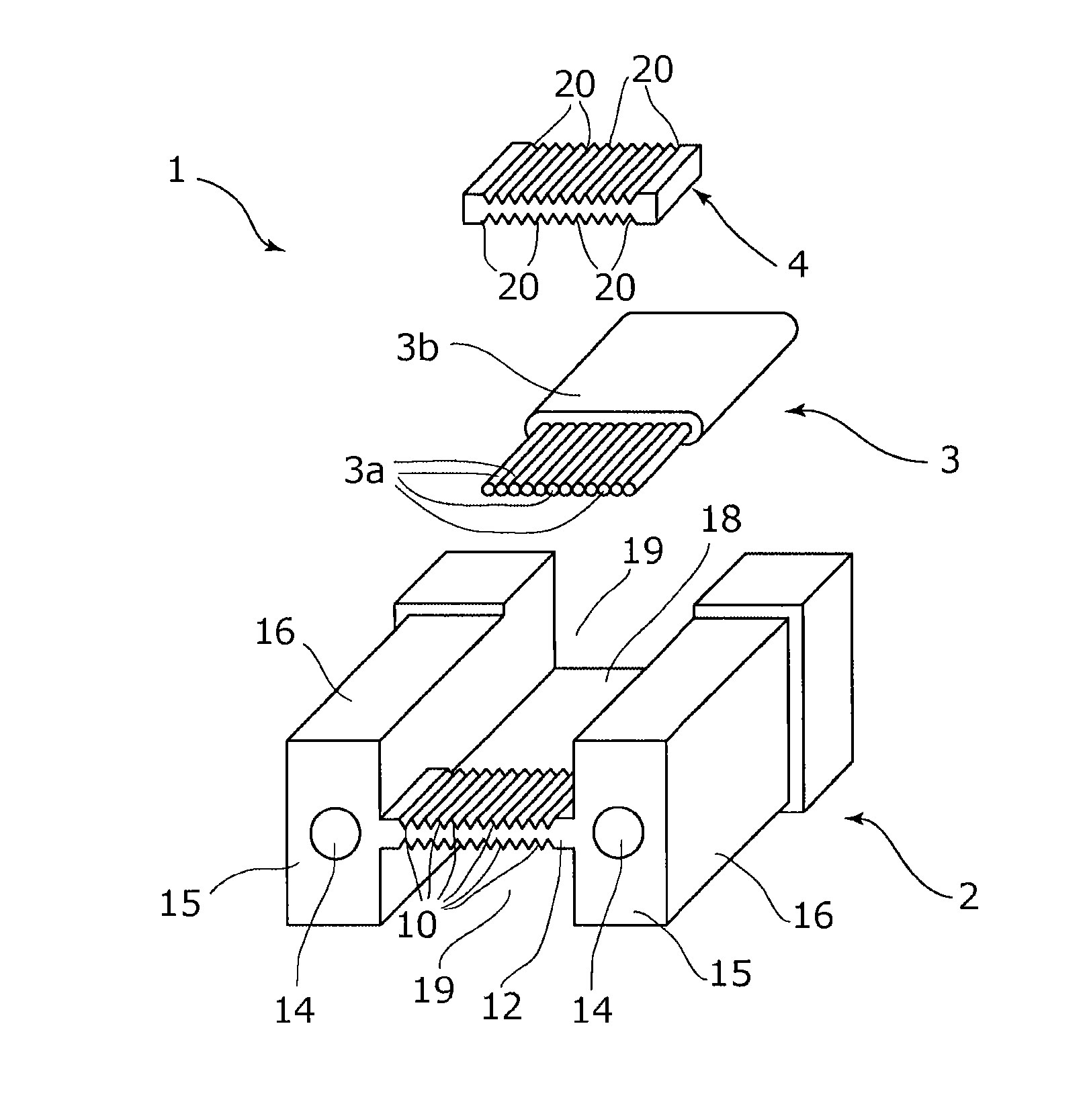
[0050]FIG. 1A is an exploded perspective view illustrating the assembly process of an optical connector ferrule 1 according to the first embodiment of the present invention, and FIG. 1B is a front view illustrating the optical connector ferrule 1 of FIG. 1A in which four layers of optical fiber ribbons 3 are stacked.

[0051]The optical connector ferrule 1 illustrated in FIG. 1A has a housing part 2 and a second alignment board 4. The housing part 2 has a first alignment board 12.

[0052]An optical fiber ribbon 3 is a multi-fiber ribbon arranged on the optical connector ferrule 1. The optical fiber ribbon 3 is such that a plurality of optical fibers (optical core fibers) is arranged in one direction and covered with a cover. The cover at an end of the optical fiber ribbon 3 is removed by a predetermined length and exposed to make bare fiber parts 3a appear, which are arranged accurately in a plurality of holding grooves 10 of the housing part 2 of the optical connector ferrule 1. Here, t...

second embodiment

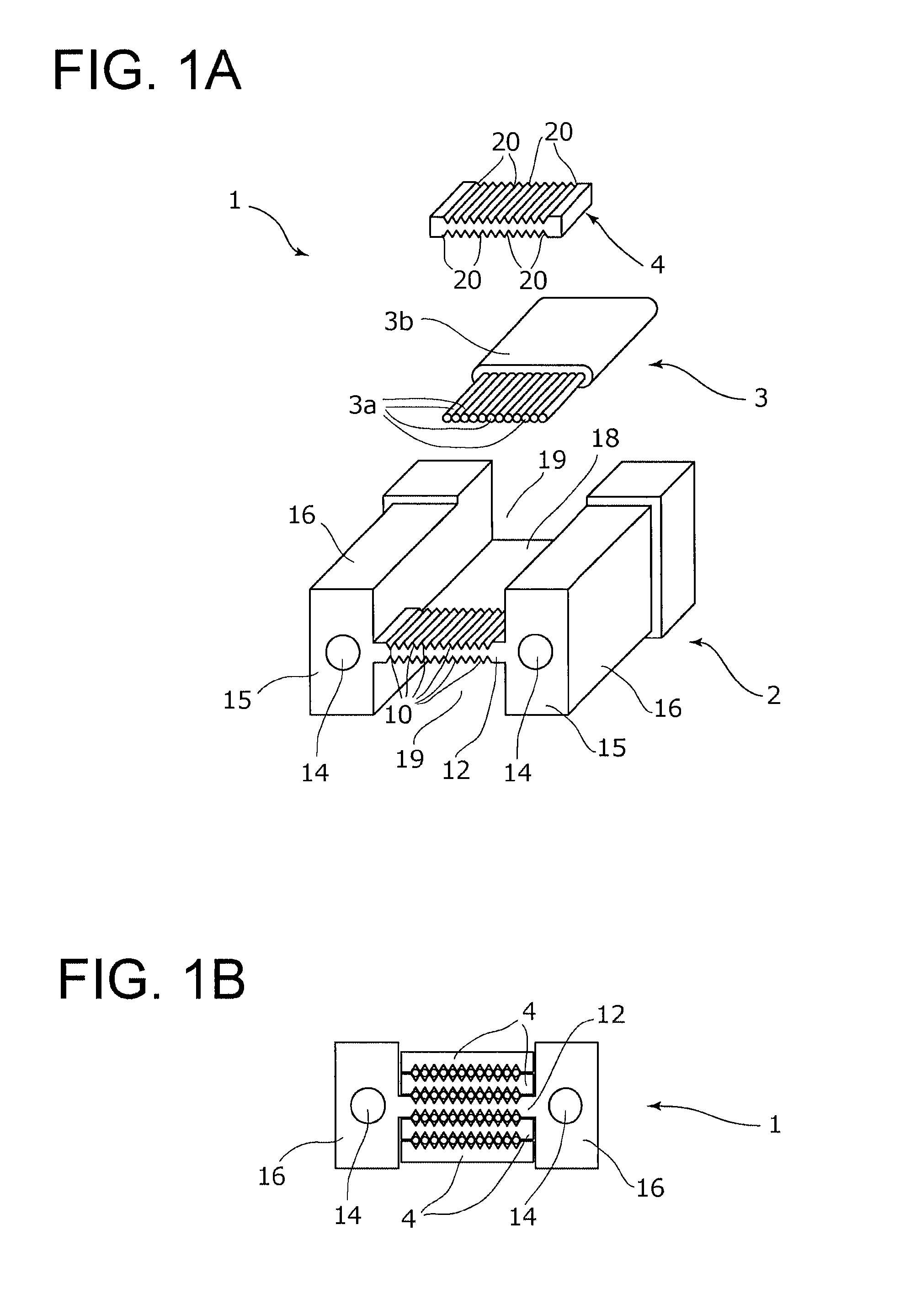
[0068]Next description is made, with reference to FIGS. 2A and 2B, about an optical connector ferrule 1 according to the second embodiment of the present invention. In the following description, like elements as those in the first embodiment are denoted by like reference numerals and its explanation is omitted here. FIG. 2A is an exploded perspective view illustrating the assembly process of an optical connector ferrule 1b according to the second embodiment of the present invention and FIG. 2B is a front view illustrating the optical connector ferrule 1b shown in FIG. 2A with four optical fiber ribbons 3 stacked.

[0069]The second embodiment shown in FIG. 2A is different from the first embodiment shown in FIG. 1A in that the housing part 2 is integrally formed in the first embodiment while the housing part 2 is formed of two separate parts, that is, a front housing part 2a and a back housing part 2b. The front housing part 2a has the first alignment board 12 and the back housing part ...

third embodiment

[0075]Next description is made, with reference to FIGS. 3A and 3B, about an optical connector ferrule according to the third embodiment of the present invention. FIG. 3A is an exploded perspective view illustrating the assembly process of the optical connector ferrule 1c according to the third embodiment of the present invention, and FIG. 3B is a front view of the optical connector ferrule 1c of FIG. 3A in which four optical fiber ribbons 3 are stacked.

[0076]The third embodiment of FIG. 3A is different from the first embodiment of FIG. 1A in that the first alignment board 12 is positioned at a lower part between the paired side support parts

[0077]The optical connector ferrule 1c illustrated in FIG. 3A has a housing part 2c and the second alignment board 4.

[0078]The housing part 2c has a first alignment board 12c with a plurality of holding grooves 10, the paired side support parts 16, the fiber support part 18 and an open part 19c.

[0079]As illustrated in FIG. 3A, the first alignmen...


PUM


Abstract

The optical connector ferrule has a second alignment board and a housing part having a first alignment board and a pair of side support parts. The first alignment board has a surface in which bare fiber parts of a optical fiber ribbon are positioned in a width direction and has holding grooves for arranging bare fiber parts. Side support parts support ends of the first alignment board and have an open part larger than a width of the ribbon in a upper and/or lower surface side of the first alignment board. The second alignment board has a positioning part for positioning in the width direction by engaging with a part of bare fiber parts on holding grooves and a fixing part for pressing and fixing bare fiber parts. The second alignment board is arranged to face the first alignment board and to sandwich bare fiber parts.

Description

TECHNICAL FIELD[0001]The present invention relates to an optical connector ferrule used in a connecting part of optical modules such as optical semiconductors or a connecting part between optical fibers in the optical communication field.BACKGROUND ART[0002]Recently, in the high-end system such as a super computer, there is a trend for larger capacity and higher rate of communicating information due to parallel operation of plural CPUs. Between ports and systems in such a system, information signals need to be transmitted at high rates and with large capacity.[0003]However, the electric transmission system of transmitting information signals with use of electric signals has limitations as to the transmission rate, transmission loss and the like. Therefore, attention has been focused on the transmission technique with use of optical fibers and the optical interconnect technique has been expected. With this technique, high-speed and high-density wiring can be realized with light weigh...

Claims


Application Information

Patent Timeline
Patent Type & Authority Applications(United States)
IPC IPC(8): G02B6/38
CPCG02B6/3881G02B6/3676G02B6/3829G02B6/3885G02B6/3652G02B6/3696
Inventor SUEMATSU, KATSUKISAITO, TSUNETOSHIANDO, TAKAYUKIIWAYA, MITSUHIRO
Owner FURUKAWA ELECTRIC CO LTD
Why Eureka
Try Eureka