System and method for powering a hydraulic pump

a hydraulic pump and hydraulic technology, applied in the direction of hybrid vehicles, electric motor propulsion transmissions, borehole/well accessories, etc., can solve the problems of limited hydraulic pump volume, limited hydraulic pump power, and limited hydraulic pump power

Active Publication Date: 2014-01-09
GE GLOBAL SOURCING LLC
View PDF2 Cites 238 Cited by
  • Summary
  • Abstract
  • Description
  • Claims
  • Application Information

AI Technical Summary

Problems solved by technology

At least one shortcoming of using such a mechanical transmission is that the mechanical components of the transmission may be limited in how much power can be transferred from the prime mover to the hydraulic pump.
Some known mechanical transmissions are limited in the power that can be provided to the hydraulic pumps due to design limitations on the gears, pinions, shafts, torque converters, and the like, that are restricted based upon available space for the mechanical transmissions, gear ratios of the mechanical transmissions, or the like.
As a result, the volume of fluid that can be pumped by the hydraulic pump can be limited.
Given the large sizes of the mechanical transmissions and the limits on power that can be provided by the mechanical transmissions, however, a relatively large number of such mechanical transmissions and the vehicles that carry the transmissions may be needed to supply adequate power to the hydraulic pumps.
As a result, many of these vehicles, transmissions, and pumps may need to be located in relatively close proximity at a pumping location (e.g., wellhead) which can create a large degree of congestion at or near the pumping location.

Method used


Image

  • System and method for powering a hydraulic pump
  • System and method for powering a hydraulic pump
  • System and method for powering a hydraulic pump

Examples


Embodiment Construction

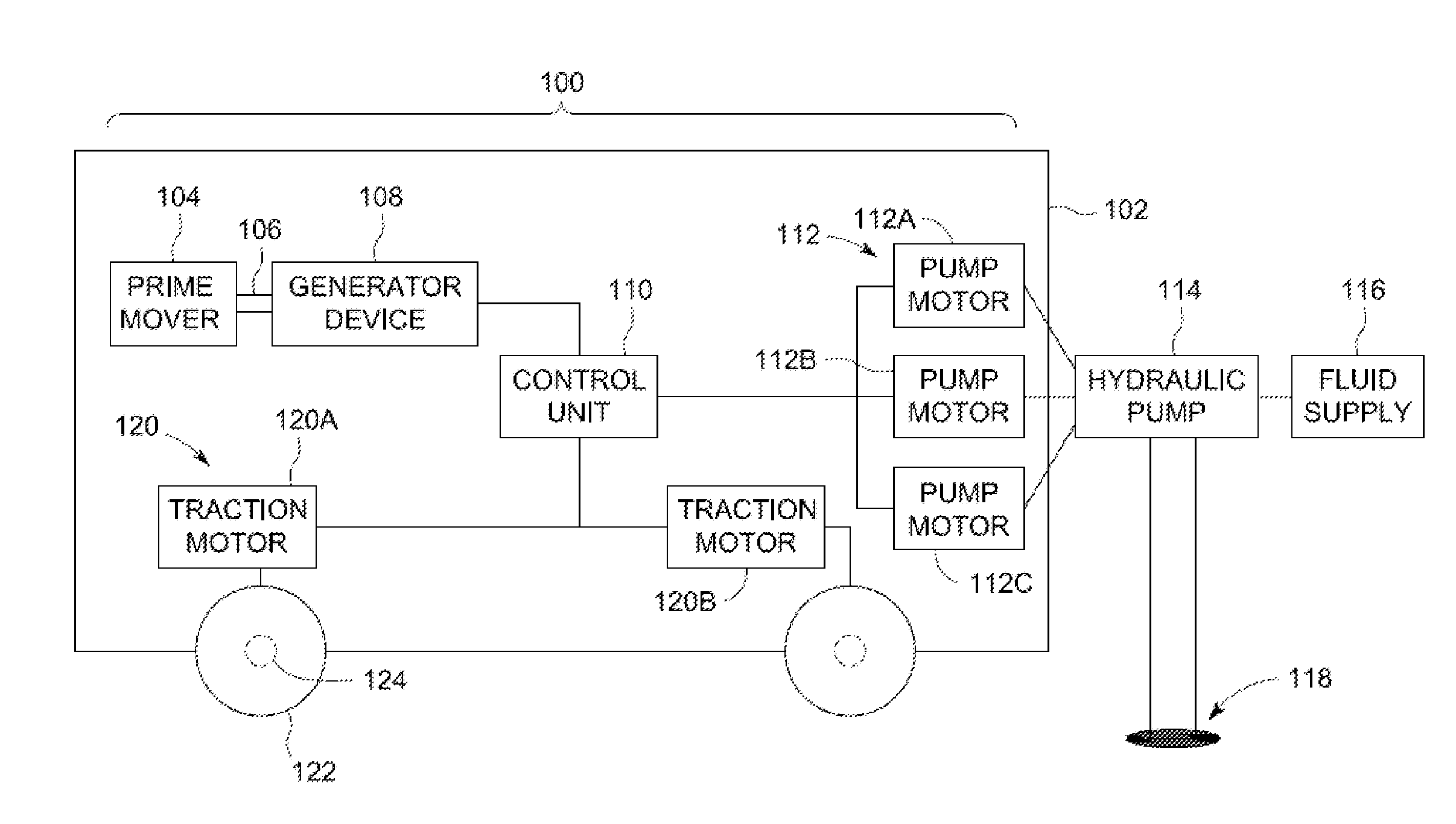
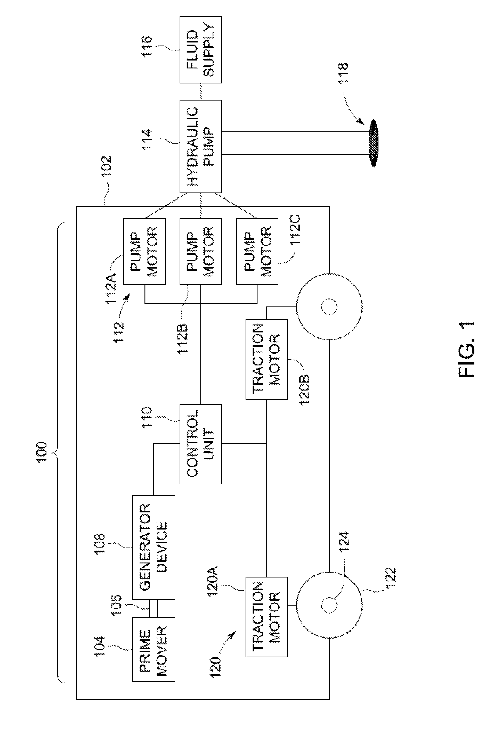
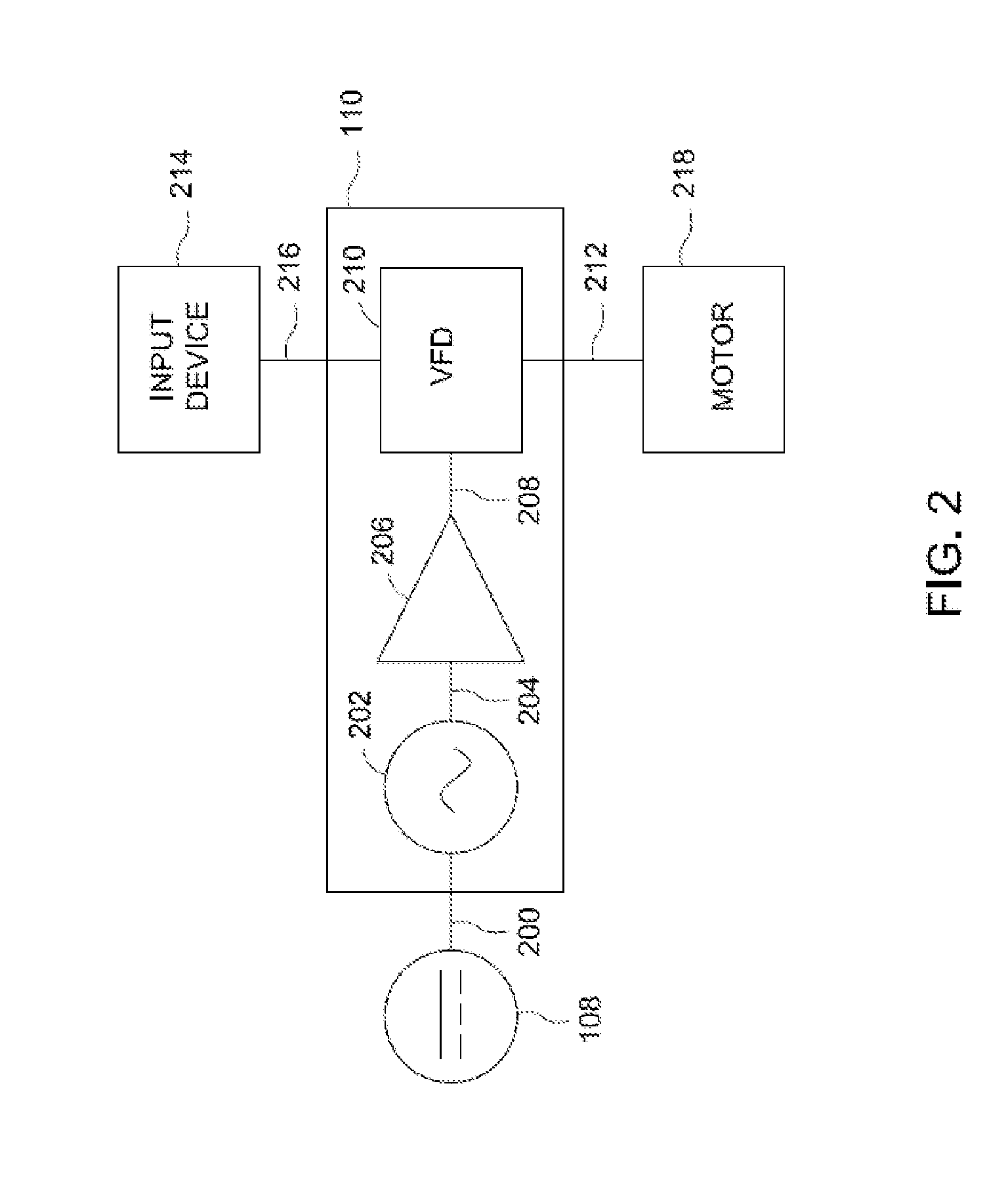
[0021]In accordance with one or more embodiments described herein, a hydraulic pump powering system is provided that includes a power source that generates or provides electric energy (e.g., such as electric current, which can include direct current and / or alternating current, an electric signal, or other electric output), electric power transmission or conversion components that modify the electric current (e.g., increase or decrease voltage, modify a frequency of the current, and the like), and pumps that are used to deliver pressurized fluids for one or more purposes, such as hydraulic fracturing, well stimulation, and the like. As one example, the power source can include a prime mover such as an internal combustion engine or gas turbine that rotates and produces torque at a controllable speed. In one embodiment, the prime mover includes a turbine that is powered by natural gas. Alternatively, the prime mover can include another device, such as an internal combustion engine. The...


PUM


Abstract

A hydraulic pump powering system includes a mobile vehicle, a first electric current generator device, and one or more electric pump motors. The mobile vehicle has first and second prime movers. The first electric current generator device is disposed onboard the mobile vehicle and is configured to be mechanically coupled with the first prime mover to convert movement created by the first prime mover into first electric current. The one or more electric pump motors are configured to receive the first electric current to power a hydraulic pump. The second prime mover is configured to generate movement that is converted into a propulsive force that propels the mobile vehicle. The one or more electric pump motors are configured to receive the first electric current in order to power the hydraulic pump to pump a fluid into a pumping location located off-board the mobile vehicle.

Description

FIELD[0001]Embodiments of the inventive subject matter described herein relate to powering hydraulic pumps.BACKGROUND[0002]Hydraulic pumps are used to pump fluids from one location to another. For example, hydraulic pumps may be used in hydraulic fracturing to pump fracturing fluid (“fracking fluid”) into a well and beneath the surface of the earth to extract resources such as natural gas from within the earth. In another example, cement pumps can be used for a variety of other pressure pumping services, such as pumping cement to a location where the cement is used to form a structure, provide an anchor or secure a casing of a bore that goes into a well, and the like. Other types of pumps, such as mud pumps that carry lubricant to flush drill cuttings from a well, also may be used.[0003]Known systems used to power these hydraulic pumps include mechanical transmissions that mechanically couple a prime mover with the hydraulic pumps. For example, some known systems include a diesel en...

Claims


Application Information

Patent Timeline
Patent Type & Authority Applications(United States)
IPC IPC(8): F04B17/03B60L11/02B60L50/10B60L50/15
CPCB60W10/30F04B17/03F04B17/05F04B17/06F04B47/02B60L50/10B60L50/15B60K6/485B60K1/04Y02T10/62E21B43/2607B60K1/00H02K7/1815H02P9/04H02P27/06B60L1/003H02K7/1823H02P9/42
Inventor CRYER, ROBERT DOUGLASWNUKOSKI, GEORGE J.KAMENSKY, DAVIDKRISHNAN, RAMESHHALLI, WILLIAMGAEY, ALEXEYMARTORELLA, RYANSHIVLANI, TARUN
Owner GE GLOBAL SOURCING LLC
Why Eureka
Try Eureka