
Drug infusion with pressure sensing and non-continuous flow for identification of and injection into fluid-filled anatomic spaces

a technology of fluid-filled spaces and injection systems, applied in the field of drugs delivery, can solve the problems of unintentional pressure on the plunger, loss of fluid into the tissues, and fluid continuously exiting out of the needle within the tissues, so as to reduce the amount of injection fluid, accurate and reproducible injection, the effect of limiting pain and tissue damag

Active Publication Date: 2014-01-09
MILESTONE SCIENTIFIC INC
View PDF2 Cites 98 Cited by
  • Summary
  • Abstract
  • Description
  • Claims
  • Application Information

AI Technical Summary

Benefits of technology

The present invention provides a method and device for accurately and safely injecting fluids into desired tissues, such as the epidural or intra-articular space. The device uses a predetermined maximum pressure value to automatically prevent continuous drug flow into surrounding tissues and will only resume fluid flow once the pressure drops below a further predetermined value, which prevents the placement of fluid into unintended tissues. The device can be used with either a pharmaceutical-containing or pharmaceutical-free fluid to identify the fluid-filled tissue space during the needle placement phase of the procedure. The use of a pharmaceutical-free fluid minimizes or eliminates the delivery of the pharmaceutical to non-target tissues. In summary, the invention reduces pain, tissue damage, and the amount of injected fluid that is administered to non-target tissues.

Problems solved by technology

The pressure on the plunger will unintentionally result in an amount of fluid continuously exiting out of the needle within the tissues.
A known deficiency of this technique is loss of fluid into the tissues when the tip of the needle is in the interspinous ligament as the tissues there are not particularly dense.
Overweight patients present a greater challenge, and with the morbidly obese patient it may not be a suitable technique because of the limitations of subjective nature of this technique.
Age appears to be an additional complicating factor because of the challenge presented by the reduced size of the anatomy of the epidural tissue-space.
Small children are often subject to the more dangerous procedure of general anesthesia as a result.
Unfortunately, if the epidural procedure is not performed properly additional fluid is injected within the tissues indiscriminately while trying to determine the location of the fluid-filled epidural space.
The additional fluid released into these tissues can further complicate the identification of the fluid-filled space.
Additionally, if the Touhly needle moves once the epidural space has been located, either by removal of the syringe or inadvertent movement of the patient or doctor's hand, the needle can either be unknowingly moved outside the epidural tissue-space or at worst advanced into dura of the spinal cord producing what is termed a “wet-tap”, which can have a dangerous long-term consequences to the patient.
Even if the epidural space was initially properly located, if the needle further advances during the injection of the anesthetic solution it may deposit a bolus of anesthetic solution into the spinal cord resulting in transient or permanent nerve damage.
A major deficiency of these systems is their inability to adjust the flow rate and / or pressure of the fluid to compensate for changes in resistance throughout the system.
The device does not, however, provide a means for automatically controlling the injection pressure of fluid delivery or for aspiration of drug delivery during use.
Samples are obtained manually from a vein or organ that is close to the surface of the skin by trained personnel, but there are problems inherent with these processes.

Method used


Image

  • Drug infusion with pressure sensing and non-continuous flow for identification of and injection into fluid-filled anatomic spaces
  • Drug infusion with pressure sensing and non-continuous flow for identification of and injection into fluid-filled anatomic spaces
  • Drug infusion with pressure sensing and non-continuous flow for identification of and injection into fluid-filled anatomic spaces

Examples


Embodiment Construction

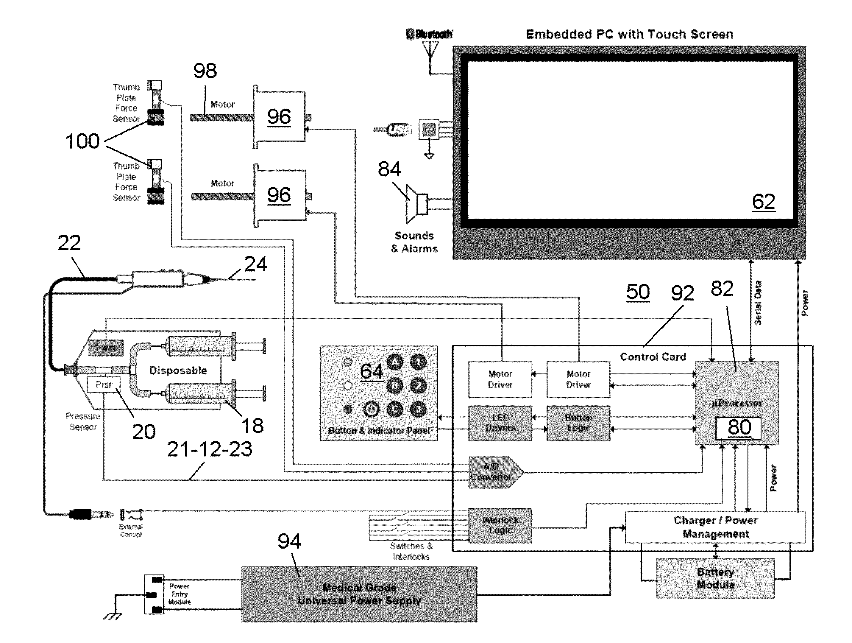
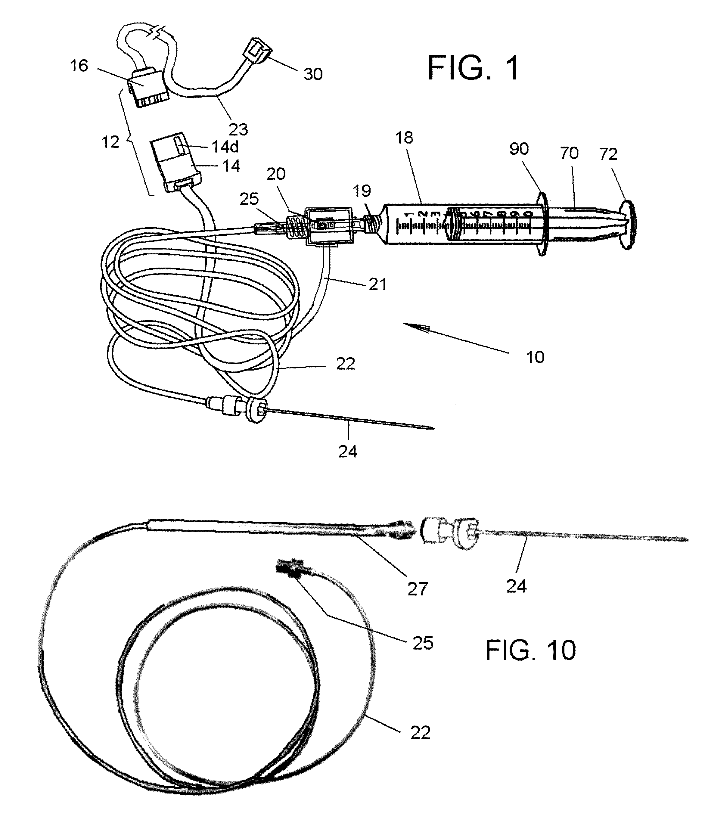
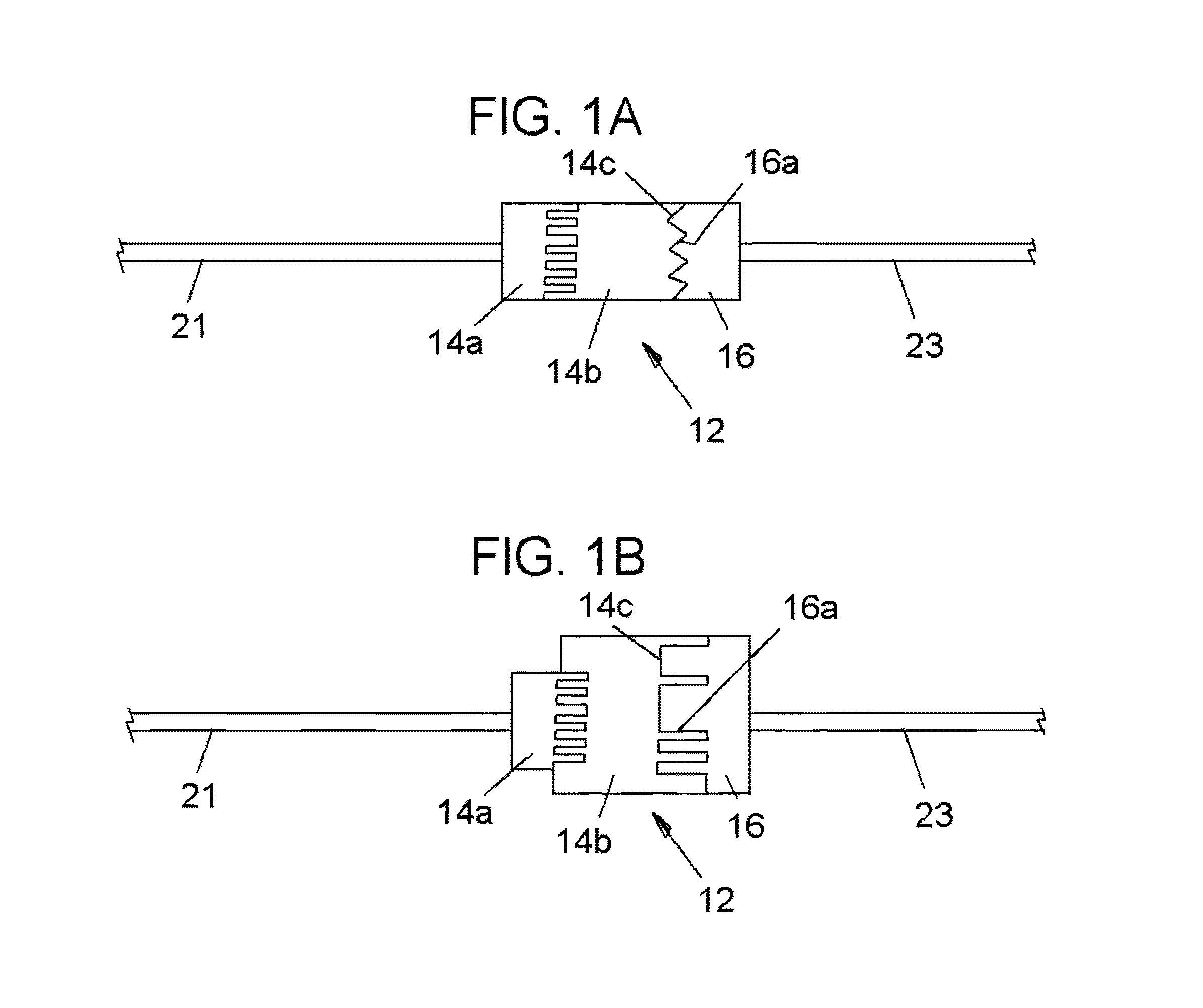
[0059]Referring now to the drawings, in which like reference numerals are used to refer to the same or similar elements, FIG. 1 shows as disposables assembly 10, made up of various parts that are permanently connected to each other and are supplied in sterile package for single use in conjunction with a computer-controlled drug delivery instrument or drive unit 50 shown in FIGS. 2 and 3, which together form a system schematically shown in FIG. 4.

[0060]The subject invention pertains to a system for determining location and delivering drugs in fluid-filled tissues such as the epidural space, intra-articular space, globe of the eye, cysts, vessels and other fluid-filled spaces of the body. The injection of such drugs, such as, but not limited to local anesthetic solutions as, cortico-steroids, hydroxyapatite, joint replenishment drugs, sclerosing agents and other drugs are typically injected into a fluid-filled tissue space for therapeutic purposes. Importantly, due to a variety of fac...


PUM


Abstract

An automatic injection apparatus uses non-continuous fluid-flow of drugs to identify an intended injection site and includes a drive mechanism, a sensor and a controller for establishing fluid flow and pressure and preventing fluid flow until the pressure drops below a predetermined threshold. The pressure threshold is determined based on an internal pressure generated during an injection and more fluid will not flow until it drops below a predetermined pressure. An injection is performed to establish an initial pressure threshhold and then to stop the fluid flow into a patient until the pressure drops below a predetermined pressure which allows fluid flow to resume, thus identifying a fluid filled tissue space. The initial pressure threshold is used as a control parameter to a microprocessor below which controls the rate of injection. Fluid flows below certain pressures are also used to identify a specific location within the body during injections.

Description

FIELD AND BACKGROUND OF THE INVENTION[0001]The present invention relates generally to improvements to the delivery of drugs, particularly to systems for subcutaneous injection / aspiration into a fluid filled space of the body. More specifically the invention provides a method and device to identify a fluid-filled tissue space of the body by stopping fluid flow based on a predetermined pressure measurement and resuming fluid flow once the pressure drops below a predetermined pressure measurement.[0002]A regional anesthesia block of epidural tissue-space is understood to produce effective transient anesthesia of the lower extremities of the body. It can be effectively used for a vast number of invasive procedures of the body, including but not limited to child birth, prosthetic hip replacement and a variety of other surgical procedures where anesthesia below the waist is required. It can also be effectively used for treatment of chronic and acute pain including, for example, “back-pain...

Claims


Application Information

Patent Timeline
Patent Type & Authority Applications(United States)
IPC IPC(8): A61M5/168A61M19/00A61F9/00
CPCA61F9/0008A61M5/168A61M19/00A61B5/032A61M2205/581A61M2205/583G16H20/17A61M5/178A61M2005/1588A61M2205/6018A61M2205/6045A61M2205/52A61M5/00A61M31/00
Inventor HOCHMAN, MARK N.
Owner MILESTONE SCIENTIFIC INC
Learn More