Syringe

a technology of syringe and syringe, which is applied in the field of syringe, can solve the problems of compromising sterility, altering sealing characteristics, and posing difficulties in sterilisation, and achieves the effects of reducing the potential exposure of medicaments, increasing the number of ribs, and improving sterility

Active Publication Date: 2014-01-09
NOVARTIS PHARM CORP +2
View PDF9 Cites 37 Cited by
  • Summary
  • Abstract
  • Description
  • Claims
  • Application Information

AI Technical Summary

Benefits of technology

[0010]The body may be made from a plastic material (e.g. a cyclic olefin polymer) or from glass and may include indicia on a surface thereof to act as an injection guide. In one embodiment the body may comprise a priming mark. This allows the physician to align a pre-determined part of the stopper (such as the tip of the front surface or one of the circumferential ribs, discussed later) or plunger with the mark, thus expelling excess ophthalmic solution and any air bubbles from the syringe. The priming process ensures that an exact, pre-determined dosage is administered to the patient.
[0014]The rod may comprise at least one rod shoulder directed away from the outlet end and the backstop may include a backstop shoulder directed towards the outlet end to cooperate with the rod shoulder to substantially prevent movement of the rod away from the outlet end when the backstop shoulder and rod shoulder are in contact. Restriction of the movement of the rod away from the outlet end can help to maintain sterility during terminal sterilisation operations, or other operations in which the pressure within the variable volume chamber or outside the chamber may change. During such operations any gas trapped within the variable volume chamber, or bubbles that may form in a liquid therein, may change in volume and thereby cause the stopper to move. Movement of the stopper away from the outlet could result in the breaching of a sterility zone created by the stopper. This is particularly important for low volume syringes where there are much lower tolerances in the component sizes and less flexibility in the stopper. The term sterility zone as used herein is used to refer to the area within the syringe that is sealed by the stopper from access from either end of the syringe. This may be the area between a seal of the stopper, for example a circumferential rib, closest to the outlet and a seal of the stopper, for example a circumferential rib, furthest from the outlet. The distance between these two seals defines the sterility zone of the stopper since the stopper is installed into the syringe barrel in a sterile environment.
[0016]A stopper with such an enhanced sterility zone can also provide protection for the injectable medicament during a terminal sterilisation process. More ribs on the stopper, or a greater distance between the front and rear ribs can reduce the potential exposure of the medicament to the sterilising agent. However, increasing the number of ribs can increase the friction between the stopper and syringe body, reducing ease of use. While this may be overcome by increasing the siliconisation of the syringe, such an increase in silicone oil levels is particularly undesirable for syringes for ophthalmic use.
[0017]The rod shoulder may be arranged within the external diameter of the rod, or may be arranged outside the external diameter of the rod. By providing a shoulder that extends beyond the external diameter of the rod, but still fits within the body, the shoulder can help to stabilise the movement of the rod within the body by reducing movement of the rod perpendicular to the first axis. The rod shoulder may comprise any suitable shoulder forming elements on the rod, but in one embodiment the rod shoulder comprises a substantially disc shaped portion on the rod.
[0018]In one embodiment of the syringe, when arranged with the plunger contact surface in contact with the stopper and the variable volume chamber is at its intended maximum volume there is a clearance of no more than about 2 mm between the rod shoulder and backstop shoulder. In some embodiments there is a clearance of less than about 1.5 mm and in some less than about 1 mm. This distance is selected to substantially limit or prevent excessive rearward (away from the outlet end) movement of the stopper.
[0029]In one embodiment, the syringe is silicone oil free, or substantially silicone oil free. Such low silicone oil levels can be achieved by using uncoated syringe barrels and / or by avoiding the use of silicone oil as a lubricant for product contacting machine parts, or pumps in the syringe assembly and fill line. A further way to reduce silicone oil and inorganic silica levels in a pre-filled syringe is to avoid the use of silicone tubing in filling lines, for example between storage tanks and pumps.

Problems solved by technology

For small volume syringes, for example those for injections into the eye in which it is intended that about 0.1 ml or less of liquid is to be injected the sterilisation can pose difficulties that are not necessarily associated with larger syringes.
Changes in pressure, internal or external to the syringe, can cause parts of the syringe to move unpredictably, which may alter sealing characteristics and potentially compromise sterility.
Incorrect handling of the syringe can also pose risks to product sterility.

Method used


Image

  • Syringe
  • Syringe

Examples


Embodiment Construction

[0056]The invention will now be further described, by way of example only, with reference to the drawings.

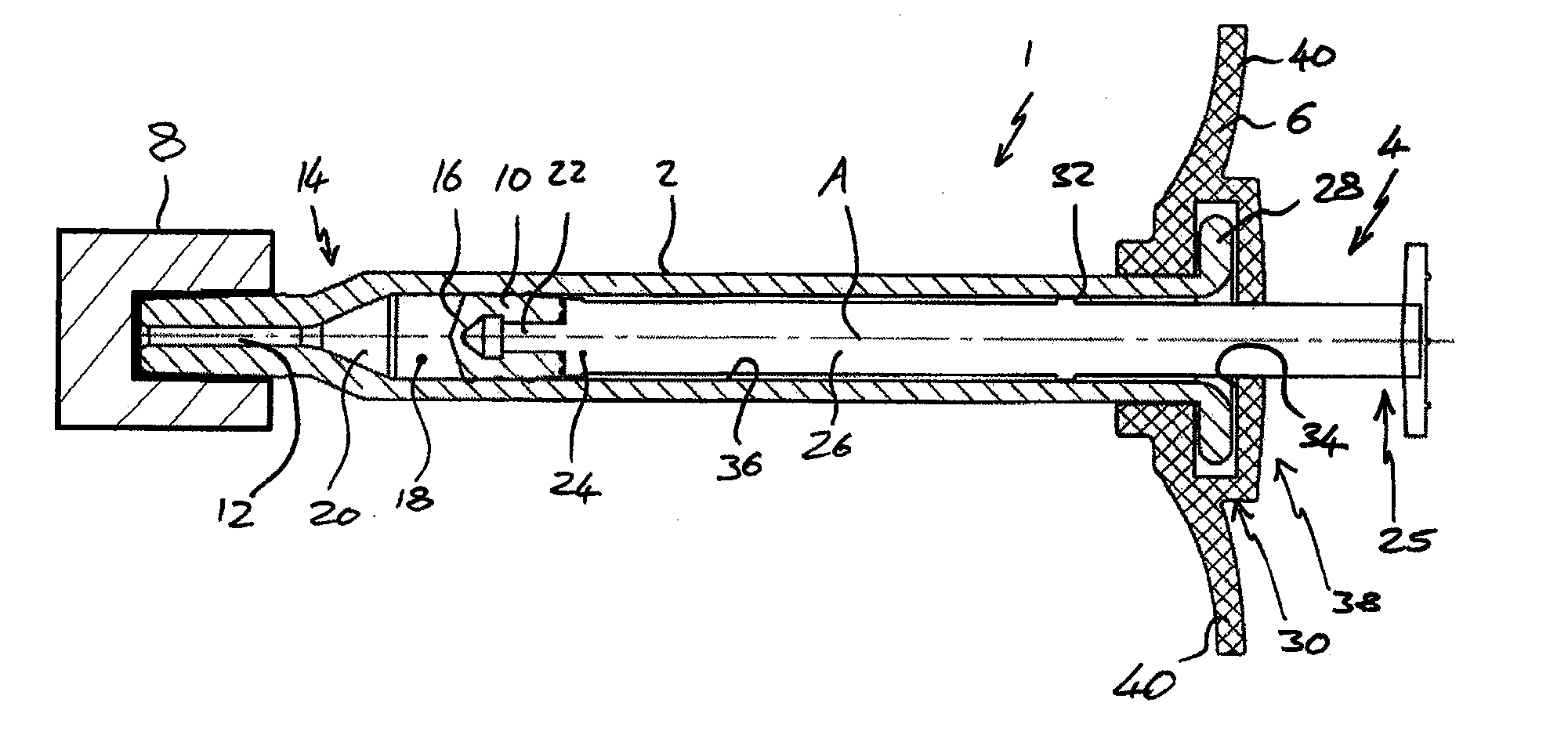
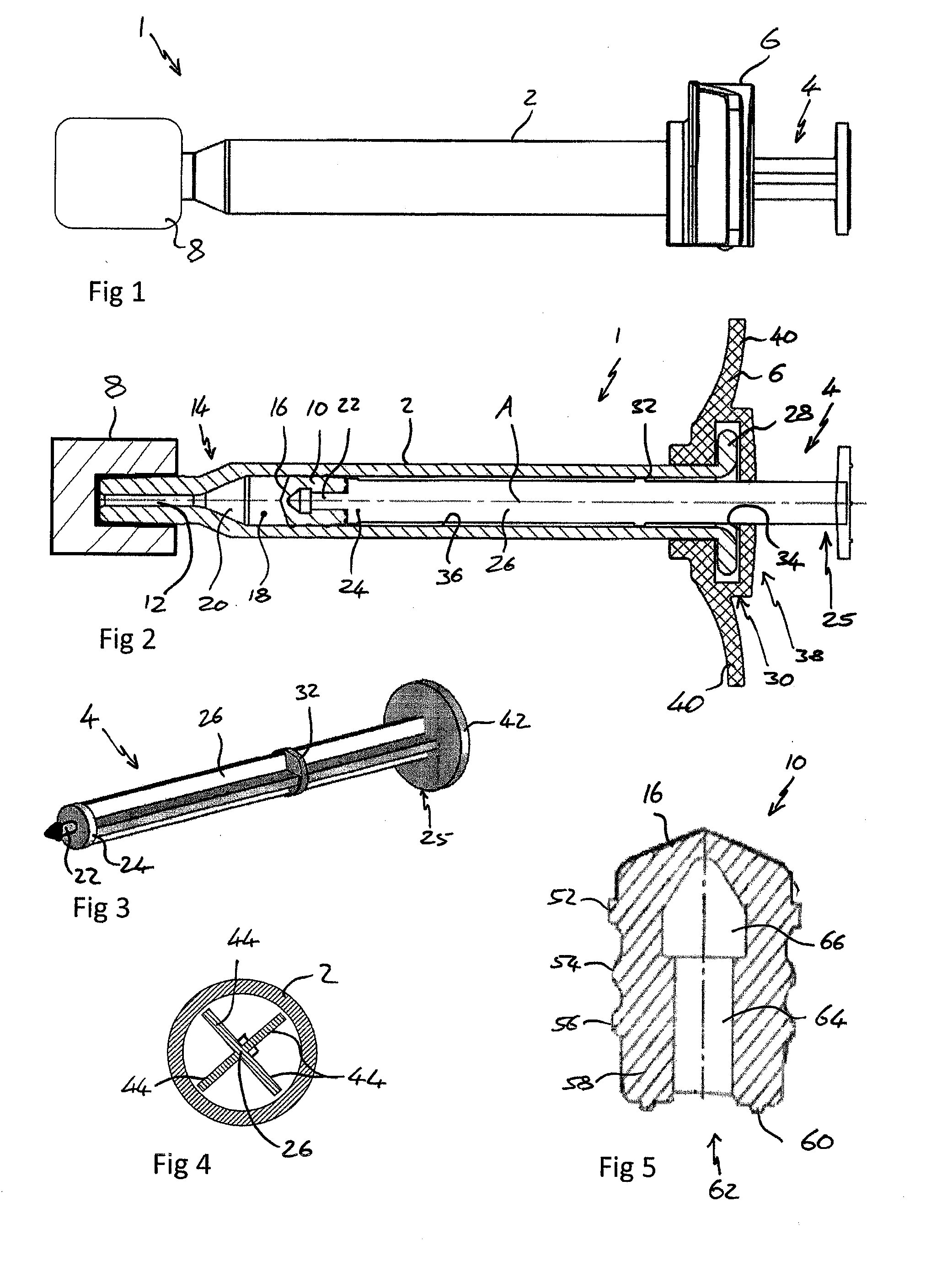
[0057]FIG. 1 shows a view from a side of a syringe 1 comprising a body 2, plunger 4, backstop 6 and a sealing device 8.

[0058]FIG. 2 shows a cross section through the syringe 1 of FIG. 1 from above. The syringe 1 is suitable for use in an ophthalmic injection. The syringe 1 comprises a body 2, a stopper 10 and a plunger 4. The syringe 1 extends along a first axis A. The body 2 comprises an outlet 12 at an outlet end 14 and the stopper 10 is arranged within the body 2 such that a front surface 16 of the stopper 10 and the body 2 define a variable volume chamber 18. The variable volume chamber 18 contains an injectable medicament 20 comprising an ophthalmic solution comprising a VEGF antagonist such as ranibizumab. The injectable fluid 20 can be expelled though the outlet 12 by movement of the stopper 10 towards the outlet end 14 thereby reducing the volume of the variable volume c...


PUM

PropertyMeasurementUnit
fill volumeaaaaaaaaaa
volumeaaaaaaaaaa

Abstract

The present invention relates to a syringe, particularly to a small volume syringe such as a syringe suitable for ophthalmic injections.

Description

TECHNICAL FIELD[0001]The present invention relates to a syringe, particularly to a small volume syringe such as a syringe suitable for ophthalmic injections.BACKGROUND ART[0002]Many medicaments are delivered to a patient in a syringe from which the user can dispense the medicament. If medicament is delivered to a patient in a syringe it is often to enable the patient, or a caregiver, to inject the medicament. It is important for patient safety and medicament integrity that the syringe and the contents of that syringe are sufficiently sterile to avoid infection, or other, risks for patients. Sterilisation can be achieved by terminal sterilisation in which the assembled product, typically already in its associated packaging, is sterilised using heat or a sterilising gas.[0003]For small volume syringes, for example those for injections into the eye in which it is intended that about 0.1 ml or less of liquid is to be injected the sterilisation can pose difficulties that are not necessar...

Claims


Application Information

Patent Timeline
Patent Type & Authority Applications(United States)
IPC IPC(8): A61F9/00A61M5/00A61M5/315
CPCA61F9/0008A61M5/31505A61M5/002A61M5/178A61M5/31513A61M2005/3104A61M2005/3139A61K9/0019A61K9/0048A61K38/179A61M5/28A61M5/31A61M5/315A61P27/02A61P35/00A61P43/00A61P9/00A61P9/10A61M5/3129A61M2210/0612A61M2005/31508A61M2005/3131
Inventor SIGG, JUERGENROYER, CHRISTOPHERBRYANT, ANDREW MARKBUETTGEN, HEINRICH MARTINPICCI, MARIE
Owner NOVARTIS PHARM CORP
Why Eureka
Try Eureka