Travel control unit of working vehicle

a technology of working vehicle and control unit, which is applied in the direction of mechanical equipment, transportation and packaging, instruments, etc., can solve the problems of hydraulic motor deceleration and rapid deceleration of working vehicle, and achieve the effect of rapid deceleration of vehicl

Inactive Publication Date: 2014-01-09
KANZAKI KOKYUKOKI MFG
View PDF9 Cites 8 Cited by
  • Summary
  • Abstract
  • Description
  • Claims
  • Application Information

AI Technical Summary

Benefits of technology

[0010]An advantage of at least of one travel control unit of a working vehicle according to the present invention is that rapid deceleration of a vehicle when an acceleration operator is displaced on a low velocity side is reduced.
[0011]An advantage of at least of one travel control unit of a working vehicle according to the present invention is that provision of a travel starting performance of the working vehicle in accordance with the user's desires is facilitated.

Problems solved by technology

Because of this, there will be no place for the hydraulic oil of the hydraulic motor to move to, causing a rapid deceleration of the hydraulic motor, and consequently, a rapid deceleration of the working vehicle.
For example, when the working vehicle is a farm tractor, if the vehicle rapidly starts to travel while the working implement such as a tiller is working on the ground, an unfavorable state of the ground, such as a rough field, may result, and the user may wish to prevent such an unfavorable state.

Method used


Image

  • Travel control unit of working vehicle
  • Travel control unit of working vehicle
  • Travel control unit of working vehicle

Examples


first preferred embodiment

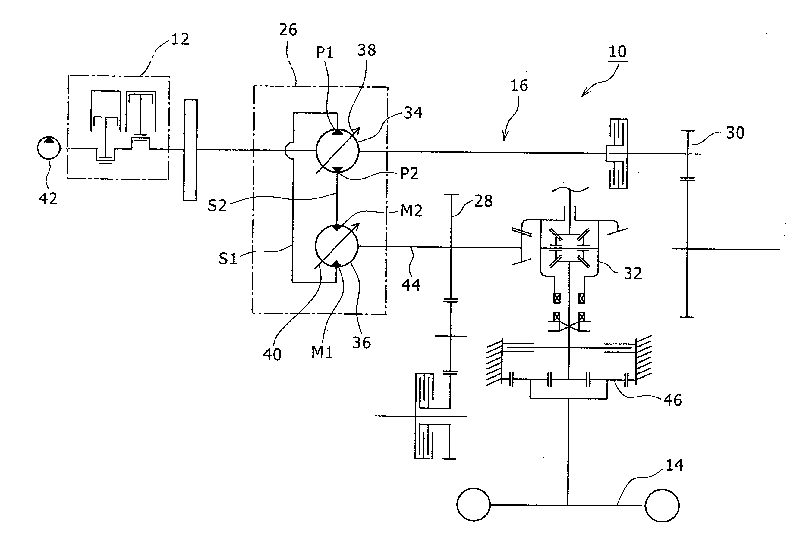
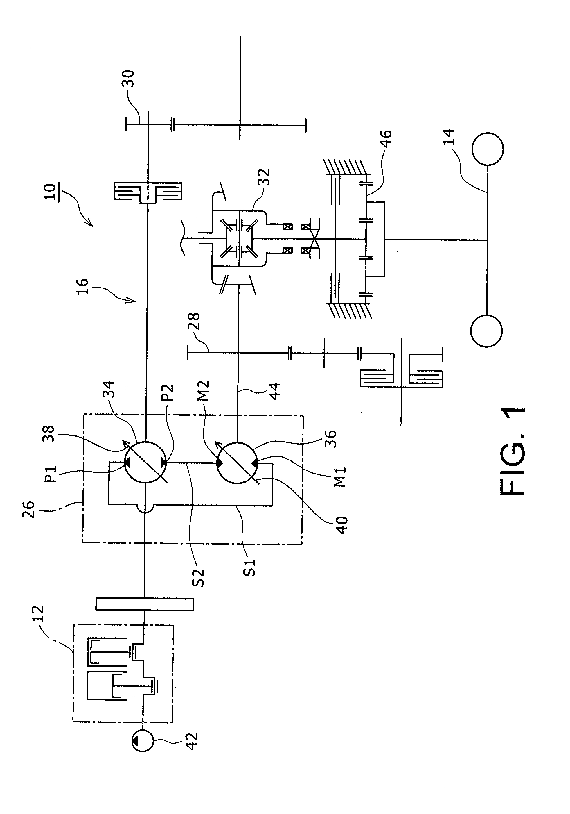
[0027]Preferred embodiments of the present invention will now be described in detail with reference to the drawings. FIGS. 1-8 are diagrams showing a first preferred embodiment of the present invention. FIG. 1 is a schematic diagram showing an overall structure of a working vehicle in which a travel control unit of a working vehicle according to the present embodiment is equipped. The working vehicle in which the travel control unit of the present embodiment is equipped may be, for example, a farm tractor for farm work, a lawnmower for mowing work, a wheel loader for public work, or the like.

[0028]As shown in FIG. 1, a working vehicle 10 comprises a vehicle frame (not shown), components supported on the vehicle frame including an engine 12, front wheels (not shown) which are a left wheel and a right wheel, and rear wheels 14 which are a left wheel and a right wheel (in FIG. 1, only one of the two wheels is shown), and a working implement (not shown) such as a tiller, a lawnmower, or...

second preferred embodiment

[0064]FIGS. 9 and 10 are diagrams showing a second preferred embodiment according to the present invention. An overall structure of a working vehicle equipped with a travel control unit of a working vehicle according to the present embodiment is similar to the structure shown in FIG. 1.

[0065]FIG. 9 is a diagram showing a hydraulic control circuit and a controller of a continuously variable transmission controlled by the travel control unit of the present embodiment. Similar to the structure of FIG. 1, the working vehicle 10 comprises a vehicle frame, an engine 12, front wheels (not shown), left and right rear wheels 13, a working implement, and a motive power transmitting apparatus 16. An acceleration pedal 18 (FIG. 9) and a brake pedal (not shown) which is a brake operator are provided on a front side of a driver seat.

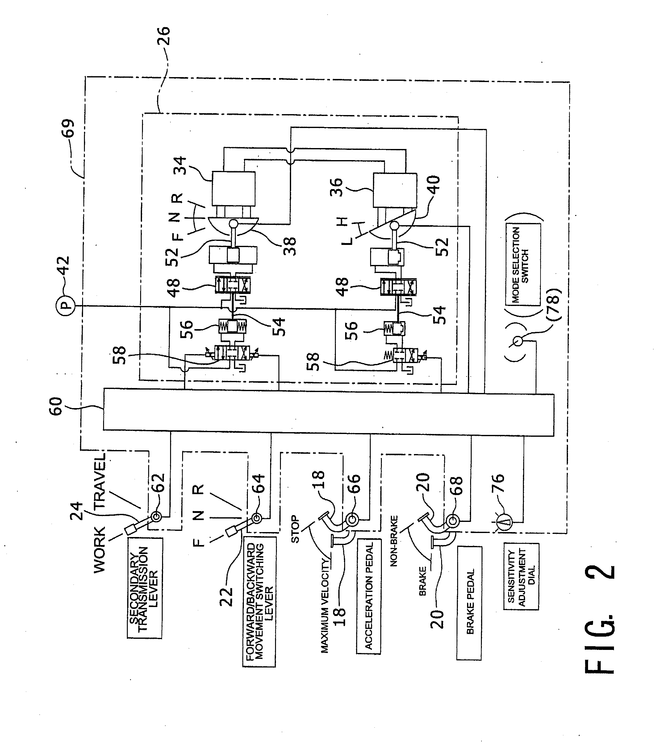
[0066]As shown in FIG. 9, similar to the structure of FIG. 2, in a casing of the HST 26, two hydraulic servo mechanisms 48 respectively corresponding to the hydraulic...

third preferred embodiment

[0084]FIG. 11 is a diagram showing capacities of the hydraulic pump and the hydraulic motor during start of travel in a third preferred embodiment of the present invention, in a comparison of the work travel and the normal travel. Basic structures of a travel control unit and a working vehicle equipped with the travel control unit of the present embodiment are similar to those in the second preferred embodiment described above. Thus, same or equivalent elements as the elements shown in FIGS. 1, 3, and 9 are assigned the same reference numerals, and portions that differ from the second preferred embodiment will primarily be described. In the second preferred embodiment, the displacement of the hydraulic motor 36 at the initial stage of starting to travel is always set at the maximum displacement. On the contrary, in the present embodiment, the displacement of the hydraulic motor 36 at the initial stage of starting to travel is set differently between the work travel and the normal tr...


PUM


Abstract

A travel control unit of a working vehicle includes an HST which is a hydraulic continuously variable transmission having a hydraulic pump and a hydraulic motor, a pedal sensor which is an operator sensor which detects a position of an acceleration pedal which is an acceleration operator, and a controller which changes a displacement of the hydraulic pump based on the position of the acceleration pedal. The controller increases the displacement of the hydraulic motor as the displacement of the hydraulic pump is reduced due to a displacement of the acceleration pedal to a low-velocity side.

Description

PRIORITY INFORMATION[0001]This application claims priority to Japanese Patent Application Nos. 2012-150321 and 2012-150373 filed on Jul. 4, 2012, which are incorporated herein by reference in their entirety.BACKGROUND[0002]1. Technical Field[0003]The present invention relates to a travel control unit of a working vehicle having a hydraulic continuously variable transmission including a hydraulic pump which is driven by an engine and a hydraulic motor which is fluidly connected to the hydraulic pump, and a controller.[0004]2. Related Art[0005]In the related art, a structure is known in which an engine and a hydraulic static continuously variable transmission (HST) are equipped in a working vehicle such as a farm tractor, a lawnmower, a wheel loader, or the like, wherein the hydraulic static continuously variable transmission includes a hydraulic pump and a hydraulic motor fluidly connected to the hydraulic pump. In this structure, the hydraulic pump is driven by an engine, and motive...

Claims


Application Information

Patent Timeline
Patent Type & Authority Applications(United States)
IPC IPC(8): F16H61/42
CPCF16H61/42F16H59/18F16H61/061F16H2061/062F16H61/421F16H61/431B60W2540/10
Inventor KAMADA, MINORU
Owner KANZAKI KOKYUKOKI MFG
Why Eureka
Try Eureka