Electromagnetic thruster

a technology of electromagnetic thruster and thruster body, which is applied in the direction of machine/engine, marine propulsion, vessel construction, etc., can solve the problems of net unbalanced force and net unbalanced force in the resonant cavity

Inactive Publication Date: 2014-01-16
CANNAE
View PDF1 Cites 11 Cited by
  • Summary
  • Abstract
  • Description
  • Claims
  • Application Information

AI Technical Summary

Benefits of technology

[0006]An exemplary embodiment of the present invention is an electromagnetic thruster, including: an axially asymmetric resonant cavity including a conductive inner surface; and a frequency generator electrically coupled to the resonant cavity. The resonant cavity is adapted to support a standing electromagnetic (EM) wave with an oscillating electric-field vector pointing

Problems solved by technology

EM interactions between the standing EM wave and the conductive inner surface of the axially-asymmetric resonant cavity create a net unbalanced force in the direction substa

Method used


Image

  • Electromagnetic thruster
  • Electromagnetic thruster
  • Electromagnetic thruster

Examples


Embodiment Construction

Overview of System Operation

[0227]FIGS. 25, 26, and 27 represent one exemplary embodiment of the present invention. A basic overview of system operation is described below.

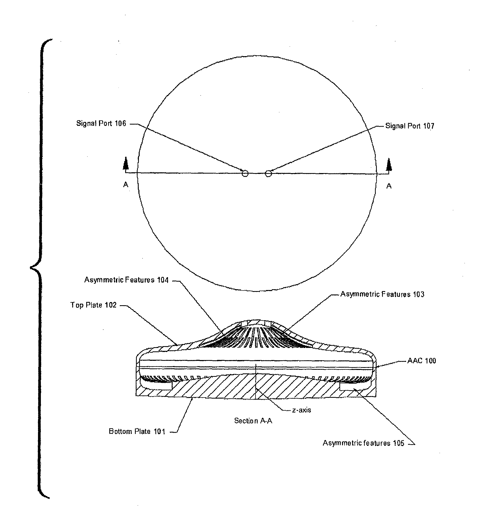
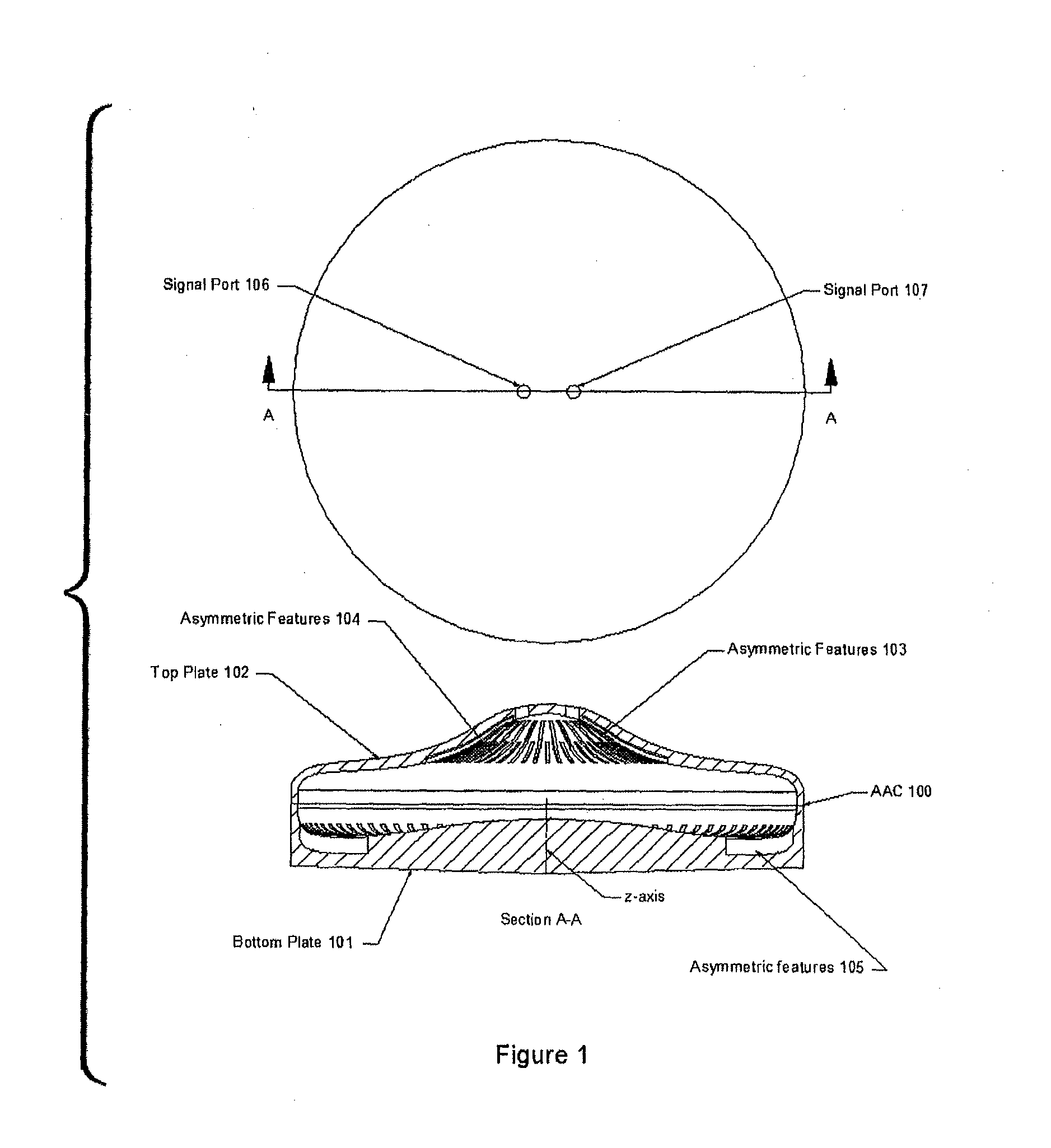
[0228]Exemplary axially-asymmetric Resonating Cavity 2700 is depicted in FIG. 27. Resonating Cavity 2700 is created by combining Top Plate 2600, depicted in FIG. 26, and Bottom Plate 2500, depicted in FIG. 25. Resonating Cavity 2700 is an axially-asymmetric resonant cavity.

[0229]A fundamental or first harmonic, resonating electromagnetic (EM) wave (i.e. a standing EM wave) may be generated within Resonating Cavity 2700. The dashed line Field Line 2701 of FIG. 27 represents one electric field maxima for the electric field of the first harmonic standing EM wave operating within Resonating Cavity 2700.

[0230]Magnetic Field Line 2501 and Magnetic Field Line 2502 of FIG. 25 represent the magnetic field direction of the first harmonic EM wave during 360 degrees of wave cycle within Resonating Cavity 2700. The magnetic fi...


PUM


Abstract

Systems and methods for electromagnetic thrusting are disclosed. An electromagnetic thrusting system includes an axially-asymmetric resonant cavity including a conductive inner surface, the resonant cavity adapted to support a standing electromagnetic (EM) wave therein, the standing EM wave having an oscillating electric field vector defining a z-axis of the resonant cavity. The resonating cavity lacks 2nd-axis axial symmetry. The standing EM wave induces a net unidirectional force on the resonant cavity.

Description

[0001]The present invention concerns propulsion systems and methods. In particular, these systems and methods use interactions between resonating electromagnetic waves and resonating cavities to achieve thrust.FIELD OF THE INVENTION[0002]The present invention concerns propulsion systems and methods. In particular, these systems and methods use interactions between resonating electromagnetic waves and resonating cavities to achieve thrust.BACKGROUND OF THE INVENTION[0003]One issue facing space exploration programs is the development of an efficient, low-mass propulsion system. The necessity of including reaction mass, as well as the mass on the engine itself, in traditional propulsion systems imposes practical limits to the range and lifetime of these propulsion systems. A number of approaches to this problem have been explored. One example of such a system is the Emdrive system.[0004]The Emdrive system is a space propulsion system that uses the differences in radiation pressure exer...

Claims


Application Information

Patent Timeline
IPC IPC(8): F02K9/00
CPCF02K9/00B64G1/409F03H99/00
Inventor FETTA, GUIDO P.
Owner CANNAE
Why Eureka
Try Eureka