Aspirator for crankcase ventilation and vacuum generation

a technology for vacuum generation and aspirators, which is applied in the field of aspirators, can solve the problems of low vacuum in the intake manifold, unsatisfactory leakage of oil pan gaskets and crankcase seals, and inability to match intake manifold vacuum characteristics, so as to simplify the control of the pcv system and reduce manufacturing and installation costs

Inactive Publication Date: 2014-01-16
FORD GLOBAL TECH LLC
View PDF11 Cites 54 Cited by
  • Summary
  • Abstract
  • Description
  • Claims
  • Application Information

AI Technical Summary

Benefits of technology

[0005]In addition to a PCV valve, an aspirator may be included in a PCV line to generate vacuum via PCV flow. Using crankcase gases as the motive flow for an aspirator may be advantageous in that it avoids the problem of saturating engine throttle control during warm idle conditions with low front end accessory drive loads. One example approach for directing a motive flow of crankcase gases through an aspirator to generate vacuum is shown in US 2011 / 0132311. In one embodiment, a PCV system is in communication with an intake manifold via an aspirator. An entraining inlet of the aspirator is in communication with a vacuum reservoir. Further, a passive control valve is arranged intermediate the PCV system and the intake manifold to limit communication from the intake manifold to the PCV system. The passive control valve is described as a having a similar flow characteristic to a PCV valve. Crankcase gases vented to the intake manifold first flow through the passive control valve, then through a motive inlet of the aspirator (drawing air from the entraining inlet), and finally leave the aspirator via an outlet. In this way, air and crankcase gases may be used to generate vacuum during positive crankcase ventilation.
[0006]The inventors herein have recognized that both vacuum generation and PCV flow regulation may be accomplished via a single component. In one example, the inventors herein have conceived of an aspirator that functions as both a PCV valve and a source of vacuum when configured in the PCV system described herein. A PCV system equipped with such an aspirator may advantageously accomplish vacuum generation and PCV flow regulation by way of a single component. Use of this multi-functioning aspirator may reduce manufacturing and installation costs and simplify control of the PCV system, while also achieving the advantages associated with the use of blowby gases for vacuum generation. Further, as this aspirator may be the only PCV valve in the system in some examples, PCV flow energy that would otherwise be expended across a PCV valve orifice may be harnessed for vacuum generation under some conditions.

Problems solved by technology

Further, blowby gases may excessively pressurize the crankcase, resulting in undesirable leakage of oil pan gasket and crankcase seals.
Such regulation may be needed because intake manifold vacuum characteristics may not match flow requirements for proper crankcase ventilation.
For example, whereas blowby production may be greatest during high load engine conditions and very light during idle and light load engine conditions, intake manifold vacuum may be low during the high load conditions and high during the idle and light load engine conditions.
Thus, intake manifold vacuum alone may not provide enough crankcase ventilation during high load conditions, yet too much crankcase ventilation may occur during idle and low load conditions due to the high intake manifold vacuum present in these conditions.
For example, if PCV flow does not vary in proportion to the regular air-fuel ratio being drawn into the intake manifold, the PCV flow may cause the air-fuel mixture drawn into the intake manifold to become too lean for efficient engine operation.
PCV systems may or may not be configured to prevent such operation, as the minimal amount of PCV backflow through the orifice in the cone may or may not pose problems for engine operation.

Method used


Image

  • Aspirator for crankcase ventilation and vacuum generation
  • Aspirator for crankcase ventilation and vacuum generation
  • Aspirator for crankcase ventilation and vacuum generation

Examples


Embodiment Construction

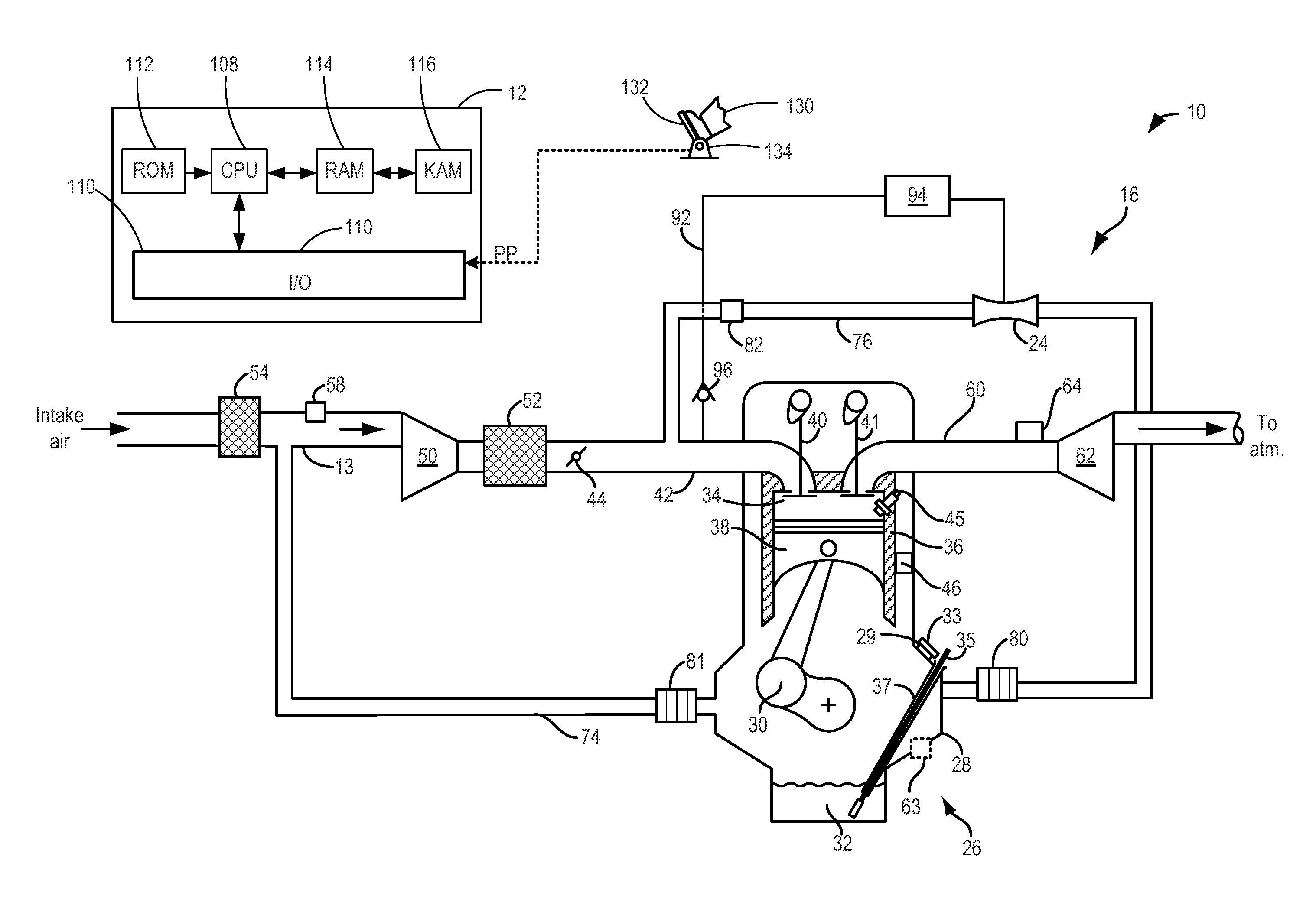
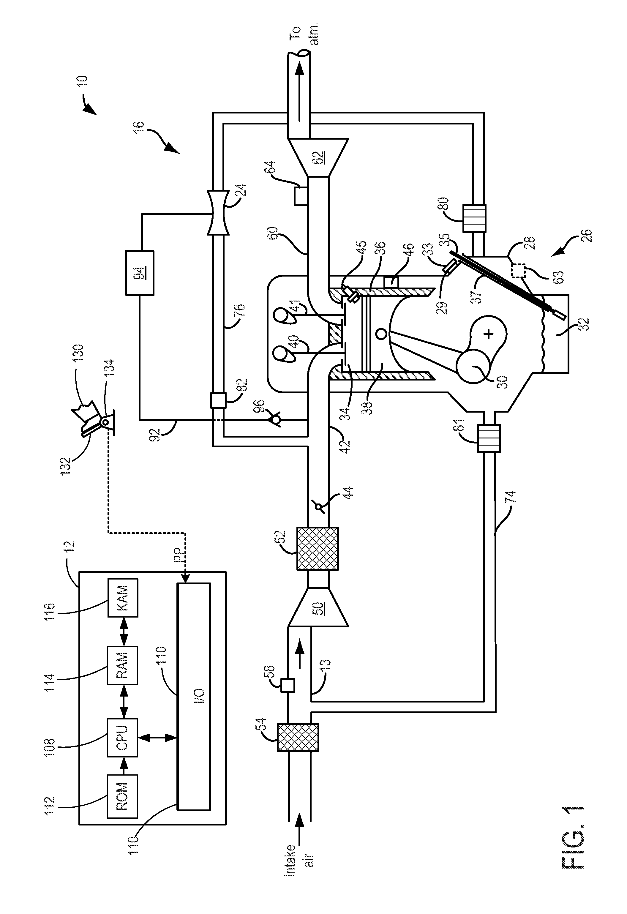
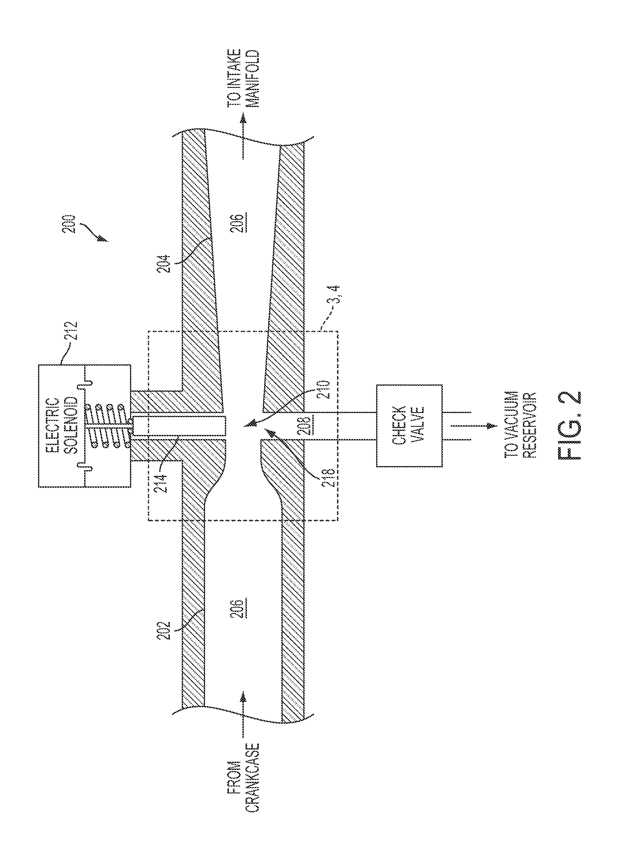
[0020]The following description relates to systems and methods for using an aspirator (e.g., the aspirator of FIG. 2 or FIG. 5) for both crankcase ventilation and vacuum generation. The aspirator may function as a PCV valve, and PCV flow through the aspirator may generate vacuum depending on a position of a pintle of the aspirator, the pintle including an orifice through which PCV flow is metered when the aspirator is fully closed. An engine controller may be structured to perform control routines, such as the methods of FIGS. 6-8, to select an aspirator operating mode and to control an actuator to move the pintle into a position corresponding to the selected operating mode and a current vacuum state, current vacuum requests, and engine constraints on aspirator flow rate. In this way, an aspirator in a PCV line coupling the crankcase and intake of an engine may serve as a PCV valve, thus reducing the need for any other means of PCV flow regulation to be included in the PCV system, w...


PUM


Abstract

Methods and systems are provided for flowing crankcase gases through an aspirator arranged in a PCV line. The aspirator regulates PCV flow, and may also generate vacuum depending on a position of a pintle extendable across a horizontal passage of the aspirator. When regulating PCV flow and not generating vacuum, the aspirator is fully closed and crankcase gases in the horizontal passage are metered through an orifice in the pintle. When generating vacuum, the aspirator is at least partially opened and PCV flow through the horizontal passage generates vacuum at a vacuum port of the aspirator.

Description

TECHNICAL FIELD[0001]This application relates to an aspirator for regulating a flow of crankcase gases into an engine intake manifold. The aspirator performs the function of a positive crankcase ventilation valve, while additionally serving as a source of vacuum under some conditions.BACKGROUND AND SUMMARY[0002]Unburned fuel and other combustion products may escape past the piston of an internal combustion engine (e.g., an internal combustion engine of a vehicle) into the crankcase. The resulting gases in the crankcase, often referred to as “blowby” gases, may contribute to the formation of sludge in the engine oil supply. Further, blowby gases may excessively pressurize the crankcase, resulting in undesirable leakage of oil pan gasket and crankcase seals.[0003]To avoid these issues, an engine may include a positive crankcase ventilation (PCV) system coupled to the intake, which serves to vent blowby gases from the crankcase to the intake. The PCV system may include a PCV valve inte...

Claims


Application Information

Patent Timeline
Patent Type & Authority Applications(United States)
IPC IPC(8): F02B25/06
CPCF01M13/022F01M13/023F01M2013/026F02B25/06Y02T10/12
Inventor BESHAY, MANSOURRUMPSA, TODD ANTHONYPURSIFULL, ROSS DYKSTRA
Owner FORD GLOBAL TECH LLC
Why Eureka
Try Eureka