Power supplying system

a technology of power supply system and power supply coil, which is applied in the direction of charging stations, electric vehicle charging technology, transportation and packaging, etc., can solve the problems of further reducing transmission efficiency, reducing transmission efficiency, and not fully suppressing transmission efficiency, so as to reduce transmission efficiency, reduce transmission efficiency, and suppress power receiving coil

Active Publication Date: 2014-01-16
YAZAKI CORP
View PDF3 Cites 15 Cited by
  • Summary
  • Abstract
  • Description
  • Claims
  • Application Information

AI Technical Summary

Benefits of technology

[0030]As explained above, according to the invention described in the first aspect, by providing a plurality of power supplying coils, the reduction of transmission efficiency caused by a gap between center axes of the power supplying coil and the power receiving coil can be suppressed. Further, when the first power supplying device supplies the electric power to only the adjacent coil detected by the position detecting device among the plurality of power supplying coils, an interference caused by supplying simultaneously the electric power to the plurality of power supplying coils is eliminated. Therefore, the reduction of transmission efficiency caused by a gap between center axes of the power supplying coil and the power receiving coil can be further suppressed. Therefore, the electric power can be supplied from the power supplying section to the power receiving section with high efficiency.
[0031]According to the invention described in the second aspect, because the position detecting device detects the adjacent coil based on signals received by the plurality of receivers, the adjacent coil can be correctly detected.
[0032]According to the invention described in the third aspect, the position detecting device detects the power supplying coil having the highest signal level of the wireless signal received from the power receiving coil as the adjacent coil among the plurality of power supplying coils. Therefore, there is no need to provide a transmitter and a receiver for transmitting and receiving the light signal or the wireless signal other than the power supplying coil and the power receiving coil. Therefore, the number of components can be reduced.
[0033]According to the invention described in the fourth aspect, the position detecting device detects the power supplying coil having the smallest reflective wave detected by the reflective wave detecting device as the adjacent coil among the plurality of power supplying coil. Therefore, the adjacent coil can be detected without transmitting the signal to the power receiving coil periodically. Therefore, the electric power can be supplied from the power supplying section to the power receiving section with higher efficiency.
[0034]According to the invention described in the fifth aspect, the reduction of transmission efficiency can be suppressed at a point where the supply of the AC power is switched from one to the other adjacent to each other.
[0035]According to the invention described in the sixth aspect, in a plane perpendicular to the axes of the plurality of power supplying coils, the reduction of transmission efficiency caused by a gap between the central axes of the power supplying coil and the power receiving coil in both an arranging direction of the power supplying coils and a direction perpendicular to the arranging direction can be suppressed.

Problems solved by technology

However, there is a problem that even when the diameter R21 of the power supplying helical coil 7 is larger than the diameter R22 of the power receiving helical coil 8, the reduction of the transmission efficiency is not fully suppressed.
However, there is a problem that when the gaps dx, dy of the central axes C1, C2 becomes more than d1 mm, the transmission efficiency becomes reduced, and as the gaps dx, dy are larger, the transmission efficiency are further reduced.
The electric power cannot be supplied while the vehicle is stopped.

Method used


Image

  • Power supplying system
  • Power supplying system
  • Power supplying system

Examples


first embodiment

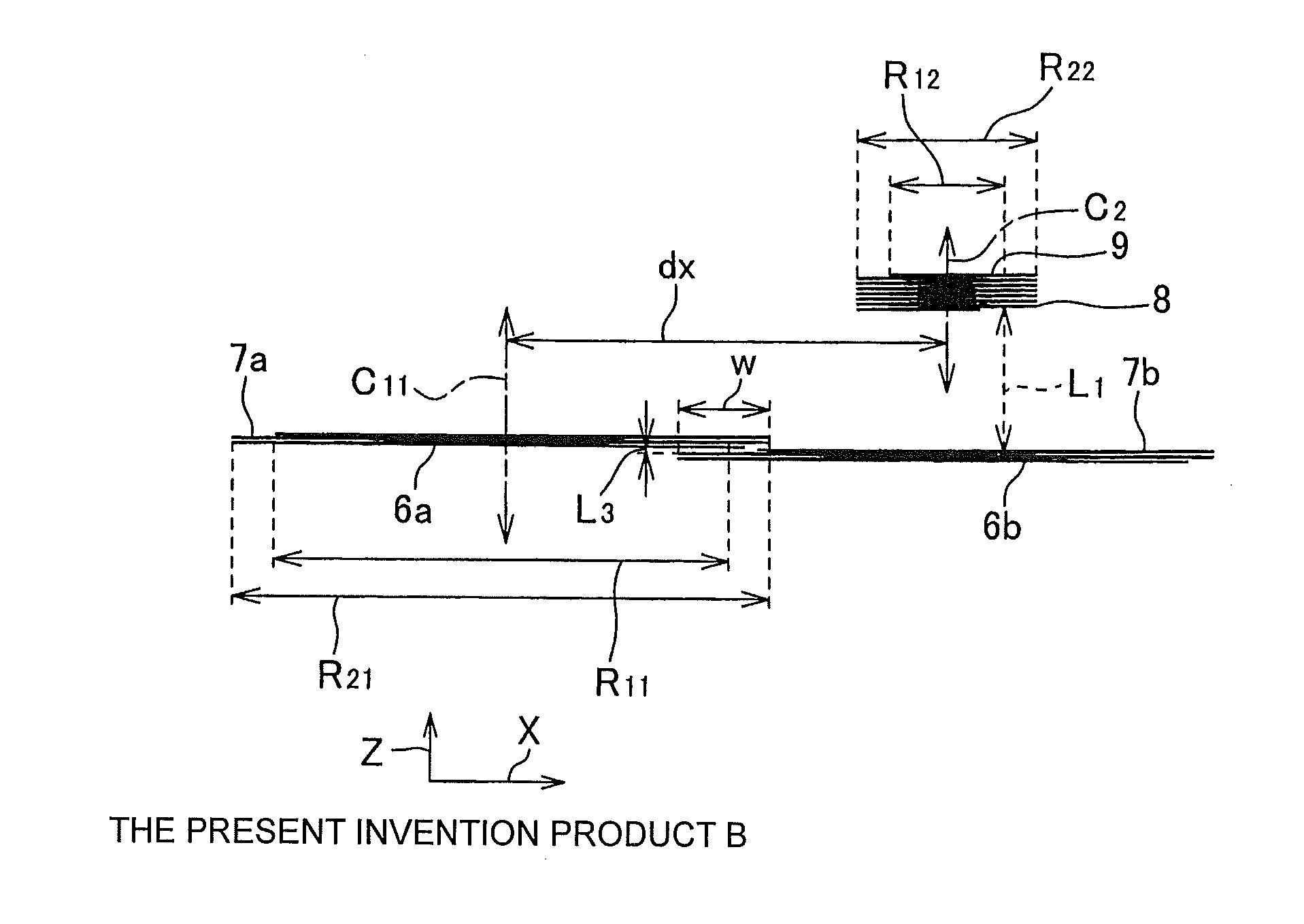
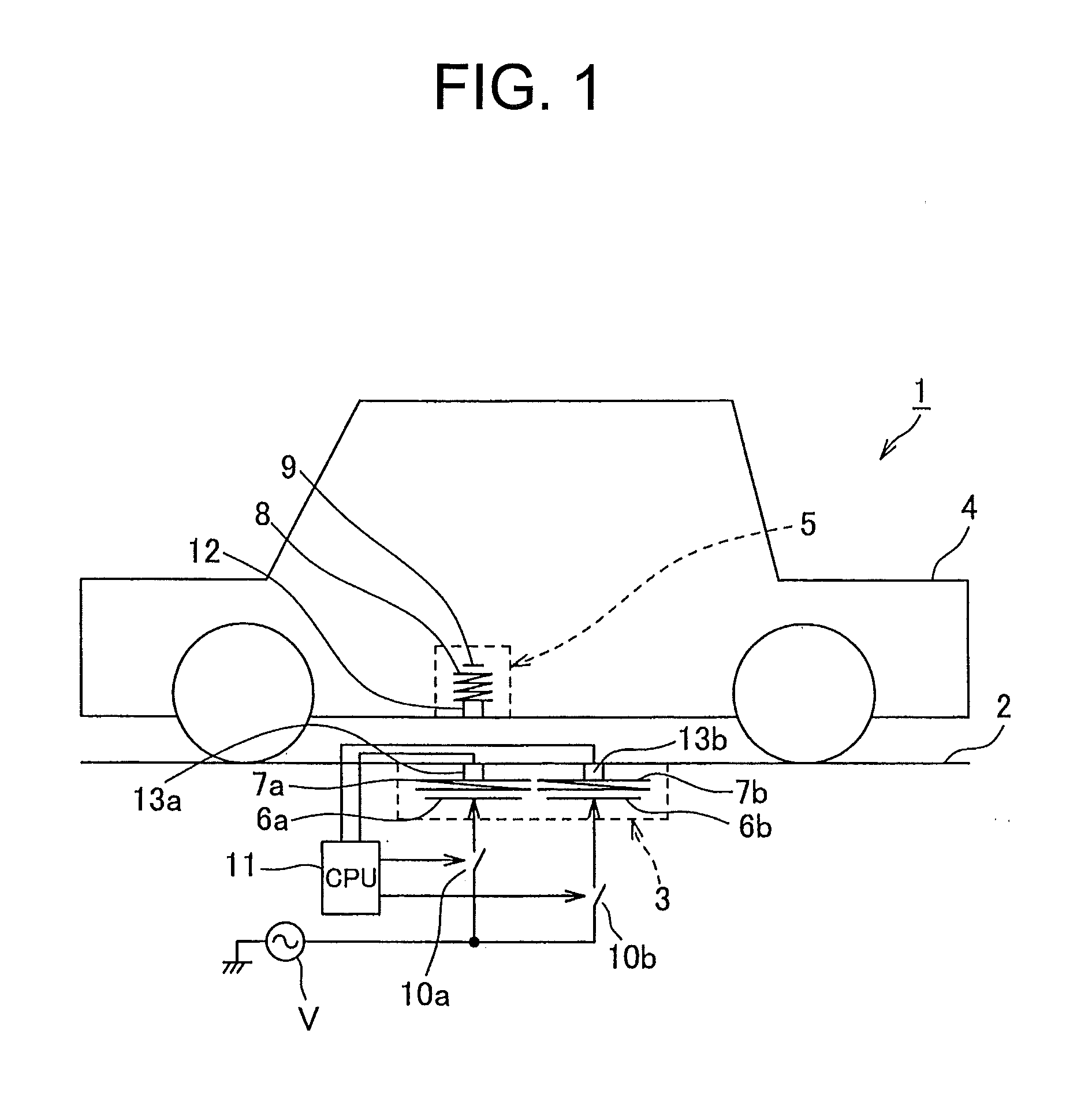
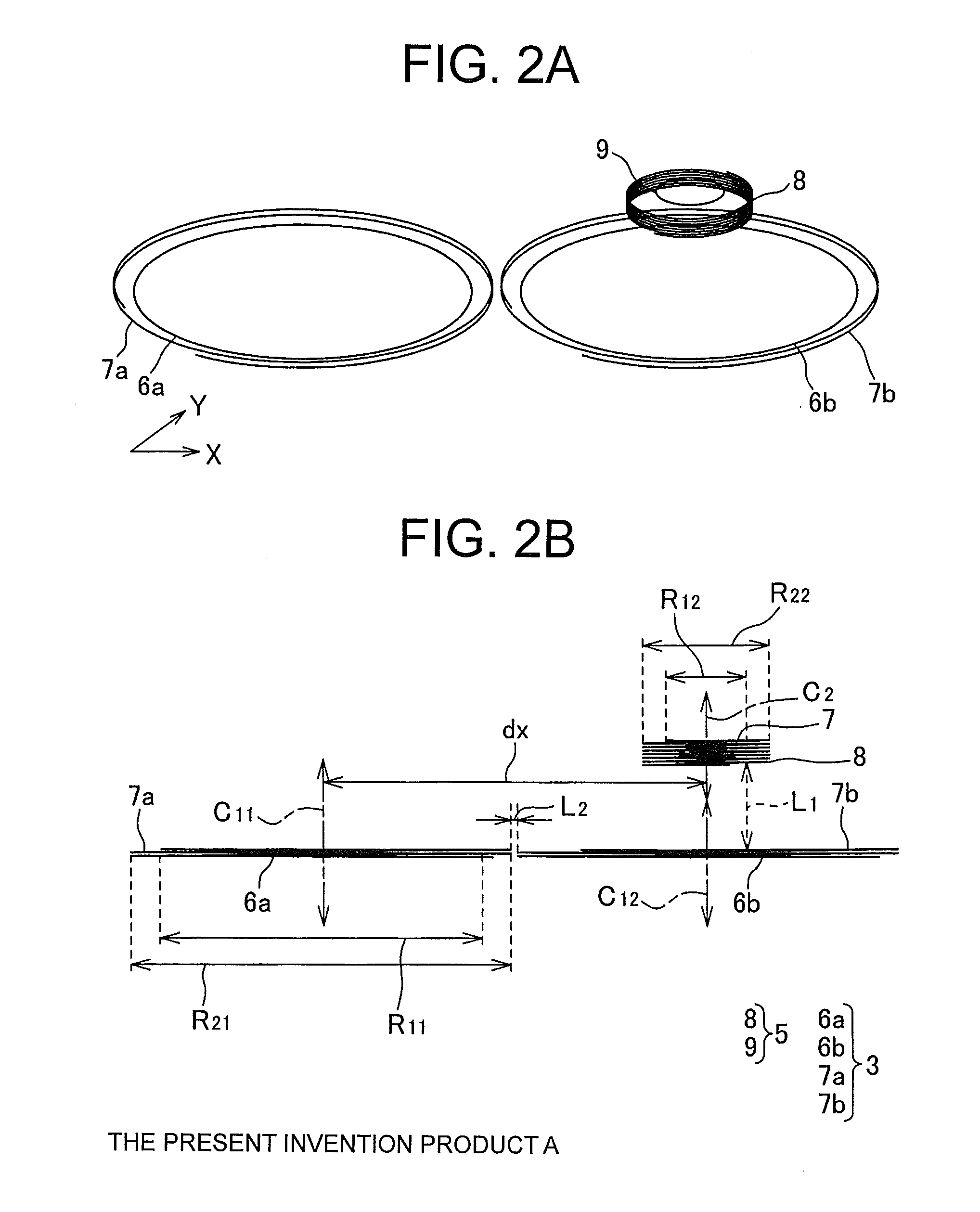
[0069]Hereinafter, a power supplying system of the present invention will be explained with reference to FIGS. 1 and 2. FIG. 1 is a schematic view showing a power supplying system according to a first embodiment of the present invention. FIGS. 2A and 2B are a perspective view and a side view showing a power supplying section and a power receiving section defining the power supplying system shown in FIG. 1. As shown in FIG. 1, a power supplying system 1 includes: a power supplying section 3 provided on a road 2 or the like; and a power receiving section 5 provided on a belly portion or the like of a vehicle 4.

[0070]As shown in FIGS. 1 and 2, the power supplying section 3 is provided with two power supplying loop antennas 6a, 6b, and power supplying helical coils 7a, 7b arranged opposite to the central axes of the power supplying loop antennas 6a, 6b with a gap and electromagnetically coupled to the power supplying loop antennas 6a, 6b.

[0071]These power supplying loop antennas 6a, 6b...

second embodiment

[0092]Next, a second embodiment will be explained. In the first embodiment described above, the transmitter 12 is arranged in the vicinity of the power receiving helical coil 8, the receivers 13a, 13b are respectively arranged in the vicinity of the power supplying helical coils 7a, 7b, and the CPU 11 detects the adjacent coil based on the light signal or the wireless signal from the transmitter 12 received by the receivers 13a, 13b. In the second embodiment, these transmitter 12, and receivers 13a, 13b are eliminated.

[0093]Namely, in the second embodiment, as shown in FIG. 4, the power supplying system 1 further includes: a transmitting circuit 14 as a transmitting device connected to both ends of the power receiving helical coil 8 and supplying electric power to the power receiving helical coil 8 to make the power receiving helical coil 8 transmit a pilot signal (see FIG. 5) as a wireless signal periodically; and receiving circuits 15a, 15b respectively connected to both ends of t...

third embodiment

[0096]Next, a third embodiment will be explained. In the third embodiment also, the transmitter 12, and the receivers 13a, 13b are eliminated. Namely, in the third embodiment, as shown in FIG. 6, the power supplying system 1 further includes: reflective wave detectors 16a, 16b as the reflective wave detecting devices respectively provided between the two power supplying loop antennas 6a, 6b and the AC source V for detecting the reflective wave from the two power supplying helical coils 7a, 7b via the power supplying loop antennas 6a, 6b to the AC source V. A directional detector, a circulator, or the like can be used as the reflective wave detectors 16a, 16b. The reflective wave detectors 16a, 16b outputs the detected reflective wave to the CPU 11.

[0097]Reflective characteristic of the power supplying helical coils 7a, 7b is degraded when the power receiving helical coil 8 is moved away from them. By using this, the CPU 11 detects the coil of which reflective wave detected by either...


PUM

PropertyMeasurementUnit
impedancesaaaaaaaaaa
distanceaaaaaaaaaa
impedanceaaaaaaaaaa

Abstract

An object of the present invention is to provide a power supplying system able to supply electric power with high efficiency from a power supplying section to a power receiving section by suppressing a reduction of transmission efficiency caused by a gap between central axes of a power supplying coil and a power receiving coil. Two power supplying helical coils are provided. When a power receiving coil is arranged opposite to the power supplying helical coils with a gap in an axis direction thereof, electric power is transmitted from the power supplying helical coils by electromagnetic resonance. A CPU detects one closest to the power receiving coil of two power supplying helical coils as an adjacent coil, and controls on/off of the switches so as to supply the electric power to only the adjacent coil.

Description

TECHNICAL FIELD[0001]The present invention relates to a power supplying system, in particular, a power supplying system for supplying electric power from a power supplying coil to a power receiving coil in a noncontact manner.BACKGROUND ART[0002]As the above power supplying system, for example, the systems shown in FIGS. 21 and 22 are known (PTL1, PTL2). As shown in FIGS. 21 and 22, a power supplying system 1 includes: a power supplying section 3; and a power receiving section 5. The power supplying section 3 is provided with a power supplying loop antenna 6 to which the electric power is supplied, and a power supplying helical coil 7 (power supplying coil) arranged opposite to the power supplying loop antenna 6 with a gap in an axial direction of the power supplying loop antenna 6 and electromagnetically bonded to the power supplying loop antenna 6. When the electric power is supplied to the power supplying loop antenna 6, the electric power is transmitted to the power supplying he...

Claims


Application Information

Patent Timeline
Patent Type & Authority Applications(United States)
IPC IPC(8): H01F38/14
CPCH01F38/14Y02T90/12Y02T90/14Y02T10/7072B60L2210/30B60L2210/40B60L2270/147B60L53/12B60L53/30B60L53/39H02J2310/48H02J50/90Y02T10/72Y02T10/70H02J50/12
Inventor KAGAMI, KAZUYOSHIHORIUCHI, SATORUTANAKA, SHINGO
Owner YAZAKI CORP
Why Eureka
Try Eureka