
Switching power supply device

Active Publication Date: 2014-01-16
FUJI ELECTRIC CO LTD
View PDF2 Cites 16 Cited by
  • Summary
  • Abstract
  • Description
  • Claims
  • Application Information

AI Technical Summary

Benefits of technology

The invention describes a switching power supply device that can control the operation of a power factor correction converter based on the load state, even when the AC voltage decreases. This prevents unintended operation of the power factor correction converter in a light load state and improves the conversion efficiency of the power factor correction converter. The device sets a second threshold voltage to prevent the feedback voltage from increasing due to a decrease in the output voltage caused by the AC voltage, and only detects the increase in the feedback voltage caused by an increase in the load. This prevents misdetducing the load state and ensures reliable operation of the power factor correction converter.

Problems solved by technology

For this reason, there is a problem that the increase of the feedback voltage FB caused by the increase of the load Po cannot be detected reliably.
In other words, when the DC voltage Vb decreases with the decrease of the AC voltage Vac, there arises such a disadvantage that it is impossible to make the originally intended control in such a manner that the increase of the load Po is detected in an operation-stopped state of the power factor correction converter 2 to thereby restart operation of the power factor correction converter 2.

Method used


Image

  • Switching power supply device
  • Switching power supply device
  • Switching power supply device

Examples


Embodiment Construction

[0038]A switching power supply device according to embodiments of the invention is described below with reference to the drawings.

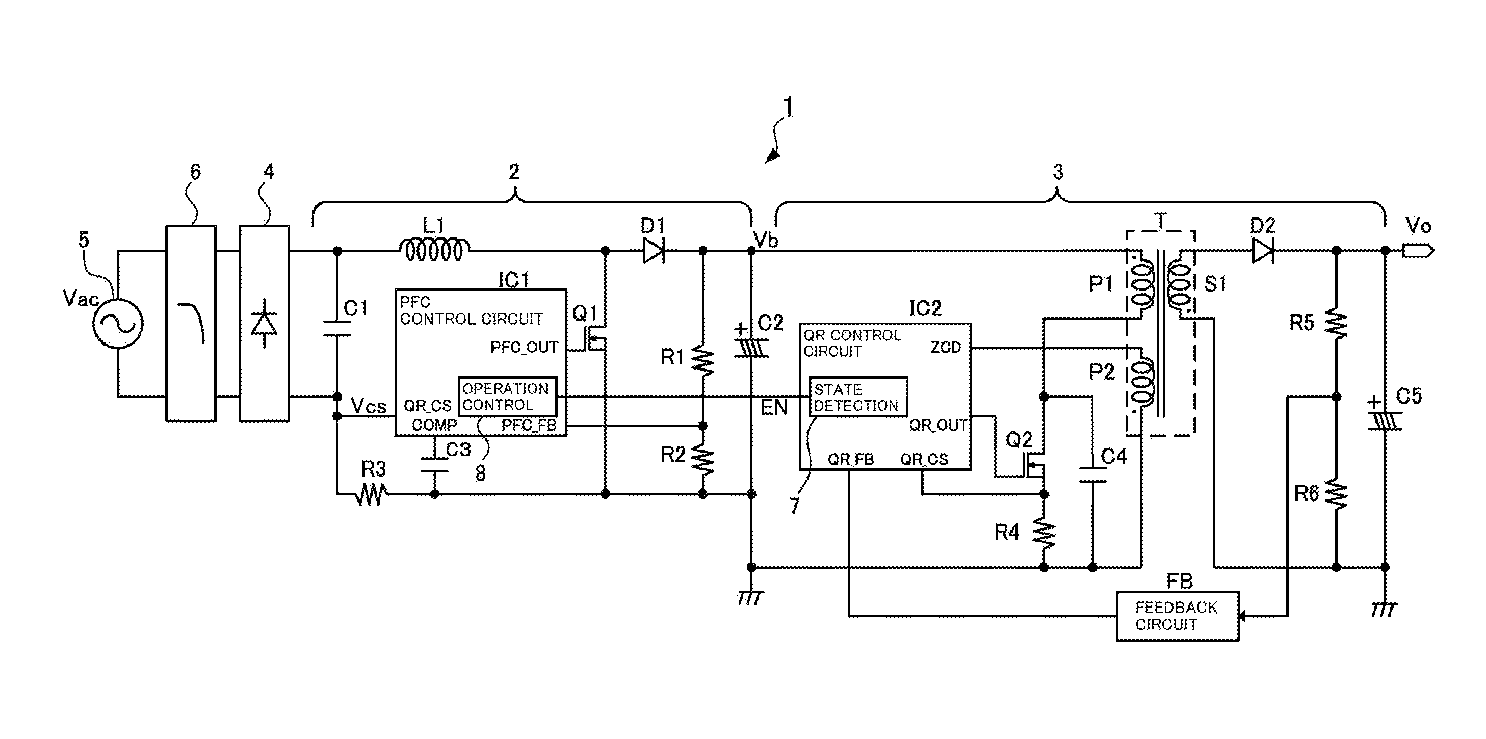
[0039]In accordance with some embodiments of the invention, the switching power supply device 1 has a power factor correction converter 2, a DC-DC converter 3 which obtains a predetermined DC output voltage Vo by switching an output voltage Vb of the power factor correction converter 2, and a load state detecting circuit 7 which outputs an operation-enable signal EN for the power factor correction converter 2 in accordance with the load state of the DC-DC converter 3 to make control to enable or stop operation of the power factor correction converter 2. The switching power supply device 1 is fundamentally configured in the same manner as the aforementioned background-art switching power supply device 1 shown in FIG. 6.

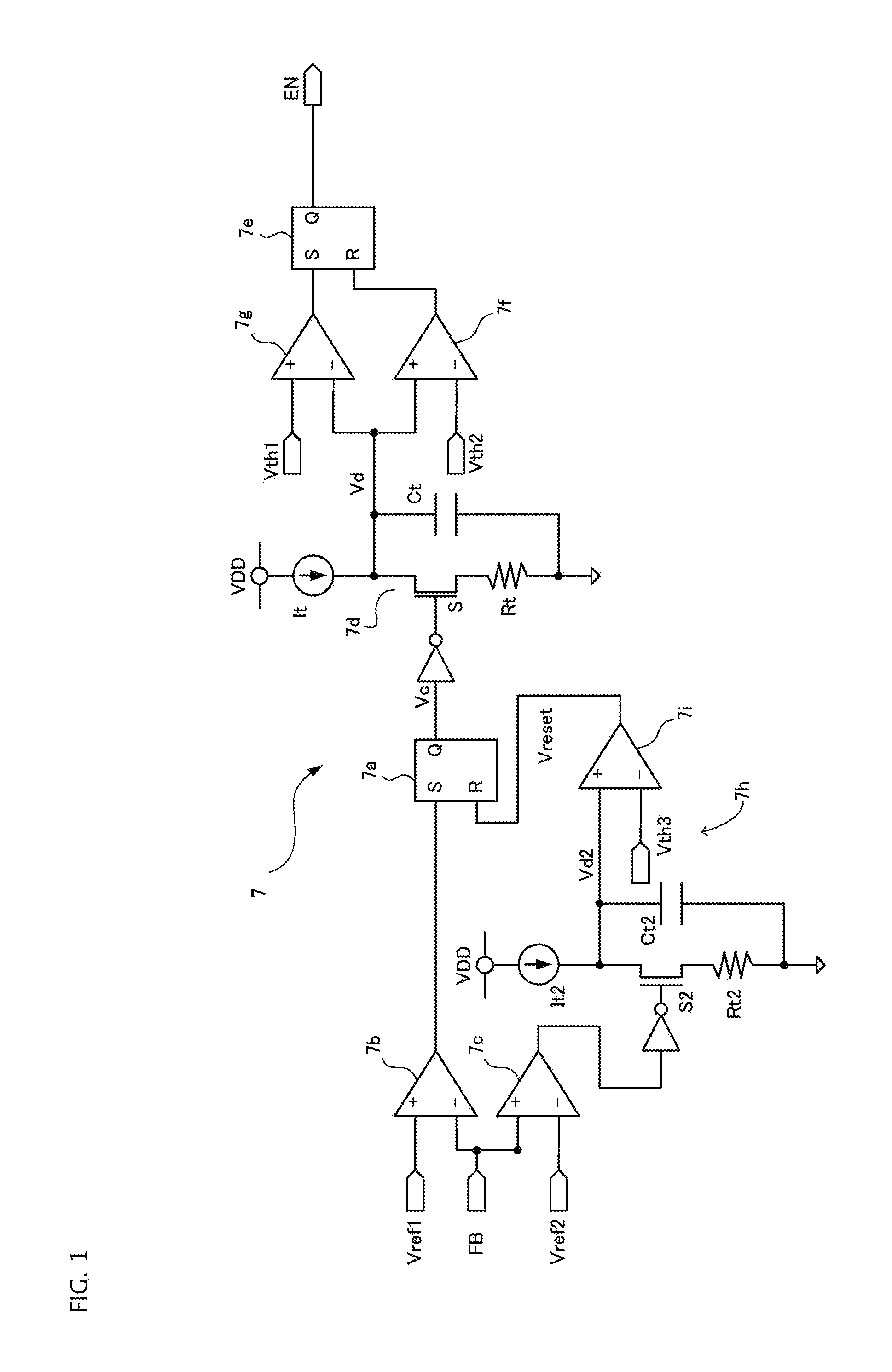
[0040]FIG. 1 is a diagram of schematic configuration of the load state detecting circuit 7 embedded in the DC-DC converter (quasi-resonant ...


PUM


Abstract

In some aspects of the invention, a load state detecting circuit is configured so that a threshold voltage for determining the size of a load of a DC-DC converter is set in the load state detecting circuit based on a maximum value of an output voltage of a power factor correction converter in an operation-stopped state of the power factor correction converter, so that the load state detecting circuit outputs an operation-enable signal when a feedback voltage indicating the size of the load of the DC-DC converter exceeds the threshold voltage. Thus, by way of some aspects of the invention, it is possible to provide a switching power supply device which can control enabling and stopping operation of a power factor correction converter reliably in accordance with a load state of a DC-DC converter obtaining a predetermined DC output voltage by switching an output voltage of the correction converter.

Description

BACKGROUND OF THE INVENTION[0001]1. Field of the Invention[0002]Embodiments of the invention relate to switching power supply devices.[0003]2. Description of the Related Art[0004]To secure stability and safety of a commercial power system, a switching power supply device which consumes power higher than 75 W is typically obligated to make power factor correction. Therefore, there has been recently proposed a switching power supply device equipped with a small-sized and highly efficient power factor correction converter (PFC) and a DC-DC converter which converts a DC voltage obtained from the power factor correction converter into a DC output voltage in accordance with specifications of a load (see, for example, Japanese patent publication no. JP-A-2007-288855). A quasi-resonant converter (QR) low in load imposed on a secondary-side rectifier diode is often used as this type DC-DC converter when the rated load is about 100 W.[0005]FIG. 6 is a diagram of schematic configuration of a s...

Claims


Application Information

Patent Timeline
IPC IPC(8): H02M3/335
CPCH02M3/33507H02M3/33515H02M1/4225Y02B70/10Y02P80/10H02M1/0032H02M1/007
Inventor CHEN, JIAN
Owner FUJI ELECTRIC CO LTD
Features
  • Generate Ideas
  • Intellectual Property
  • Life Sciences
  • Materials
  • Tech Scout
  • Unparalleled Data Quality
  • Higher Quality Content
  • 60% Fewer Hallucinations
Learn More