Constant current controller

a constant current controller and controller technology, applied in the direction of power conversion systems, dc-dc conversion, instruments, etc., can solve the problems of manufacturing cost increase and manufacturing procedures that are over-run, and achieve the effect of reducing variations

Inactive Publication Date: 2014-01-16
IMMENSE ADVANCE TECH
View PDF0 Cites 50 Cited by
  • Summary
  • Abstract
  • Description
  • Claims
  • Application Information

AI Technical Summary

Benefits of technology

[0029]Still another objective of the present invention is to disclose a constant current controller, which is capable of reducing the variations of a required average of a secondary side current by using a ratio of two resistances inside the constant current controller in generating the required average of a secondary side current.

Problems solved by technology

Although the mentioned problems can be tackled by trimming the resistance of the resistor 434 and the capacitance of the capacitor 438 in each power module, however, it will incur manufacturing cost and excess manufacturing procedures.

Method used


Image

  • Constant current controller
  • Constant current controller
  • Constant current controller

Examples


Embodiment Construction

[0070]The present invention will be described in more detail hereinafter with reference to the accompanying drawings that show the preferred embodiments of the invention.

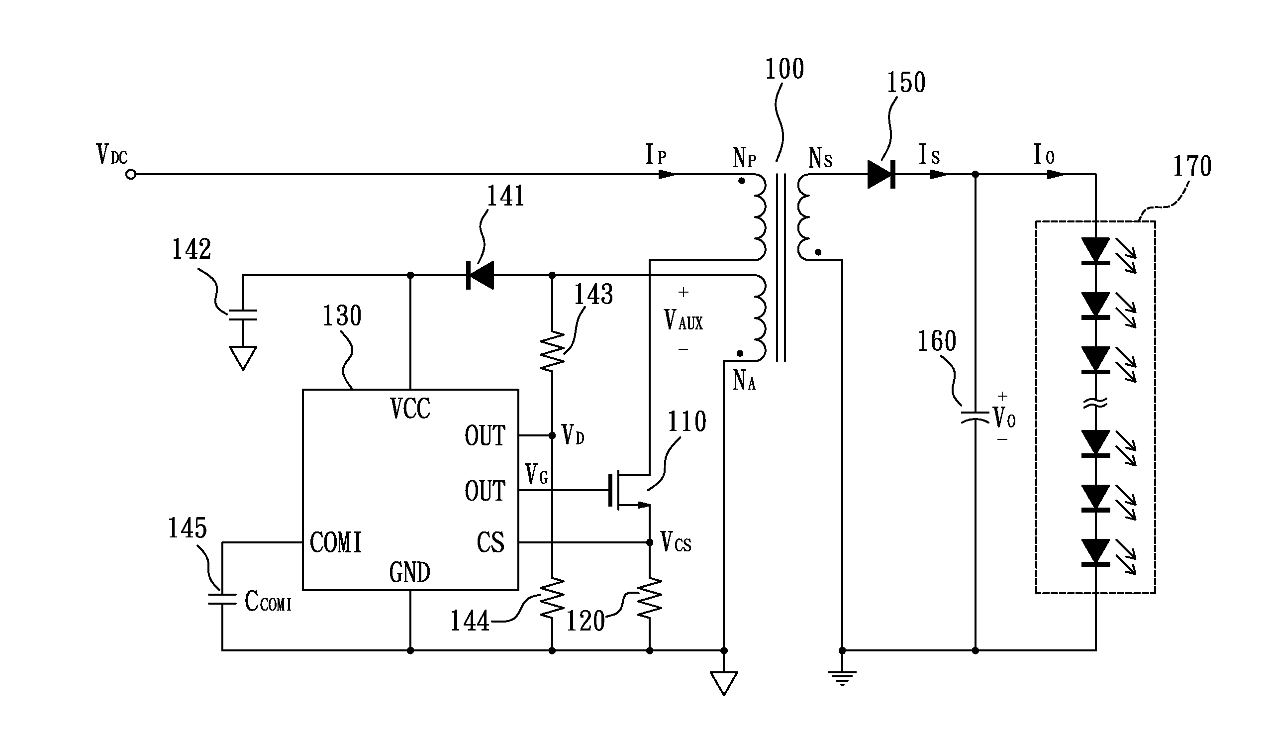
[0071]Please refer to FIG. 6, which illustrates a circuit diagram of a constant current power module including a constant current controller according to a preferred embodiment of the present invention. As illustrated in FIG. 6, the constant current power module includes a transformer 100, an NMOS transistor 110, a resistor 120, a constant current controller 130, a diode 141, a capacitor 142, resistors 143-144, a capacitor 145, a diode 150, a capacitor 160, and a LED load 170.

[0072]The transformer 100 has a primary coil of NP turns, a secondary coil of NS turns, and an auxiliary coil of NA turns.

[0073]The NMOS transistor 110 is used for controlling a primary side current IP flowing through the primary coil according to a duty ratio of a gate signal VG.

[0074]The resistor 120, connected between the NMOS transistor 110...


PUM


Abstract

A constant current controller for a constant current power module, including: a demagnetization sensing unit, used for detecting the voltage variation of a detection signal to generate a discharging time signal having an active period corresponding to a secondary side discharging time, wherein the detection signal is derived from an auxiliary coil; a secondary side current sensing unit, used for detecting a peak value of a current sensing signal, and providing an output current according to the peak value of the current sensing signal under the control of the discharging time signal, wherein the current sensing signal is corresponding to a primary side current; and an error current generator, used for generating an error current according to the difference between the output current and a reference current, wherein the error current is converted to a threshold voltage by a first capacitor.

Description

BACKGROUND OF THE INVENTION[0001]1. Field of the Invention[0002]The present invention relates to a constant current controller, especially to a constant current controller for constant current power modules.[0003]2. Description of the Related Art[0004]FIG. 1 illustrates a circuit diagram of a prior art constant current power module. As illustrated in FIG. 1, the prior art constant current power module includes a transformer 10, an NMOS transistor 20, a resistor 30, a controller 40, a diode 51, a capacitor 52, resistors 53, 54, capacitors 55, 56, a resistor 57, a diode 60, a capacitor 70, and a load 80.[0005]The transformer 10 has a primary coil of NP turns, a secondary coil of NS turns, and an auxiliary coil of NA turns.[0006]The NMOS transistor 20 is used for controlling a primary side current IP flowing through the primary coil according to a duty ratio of a gate signal VG.[0007]The resistor 30, connected between the NMOS transistor 20 and a ground, is used for generating a curren...

Claims


Application Information

Patent Timeline
Patent Type & Authority Applications(United States)
IPC IPC(8): H02M3/335
CPCH02M3/33507H02M1/0009
Inventor SU, WEI-CHUANHSIAO, WEI-CHUN
Owner IMMENSE ADVANCE TECH
Why Eureka
Try Eureka