Method of transceiving for device to device communication

a technology of device and communication channel, applied in the field of device to device communication, can solve the problems of not yet determined details of the cellular network-based d2d communication schem

Inactive Publication Date: 2014-01-16
ELECTRONICS & TELECOMM RES INST
View PDF5 Cites 61 Cited by
  • Summary
  • Abstract
  • Description
  • Claims
  • Application Information

AI Technical Summary

Benefits of technology

[0010]Accordingly, example embodiments of the present invention are provided to substantially obviate one or more problems due to limitations and disadvantages of the related art.

Problems solved by technology

However, details of the cellular network-based D2D communication scheme, such as measurement of link channel state information, a method of modulating and demodulating a data channel, a method of mapping resources of the data channel, and a design of a control channel for device-to-device communication have not yet been determined.

Method used


Image

  • Method of transceiving for device to device communication
  • Method of transceiving for device to device communication
  • Method of transceiving for device to device communication

Examples


case 1

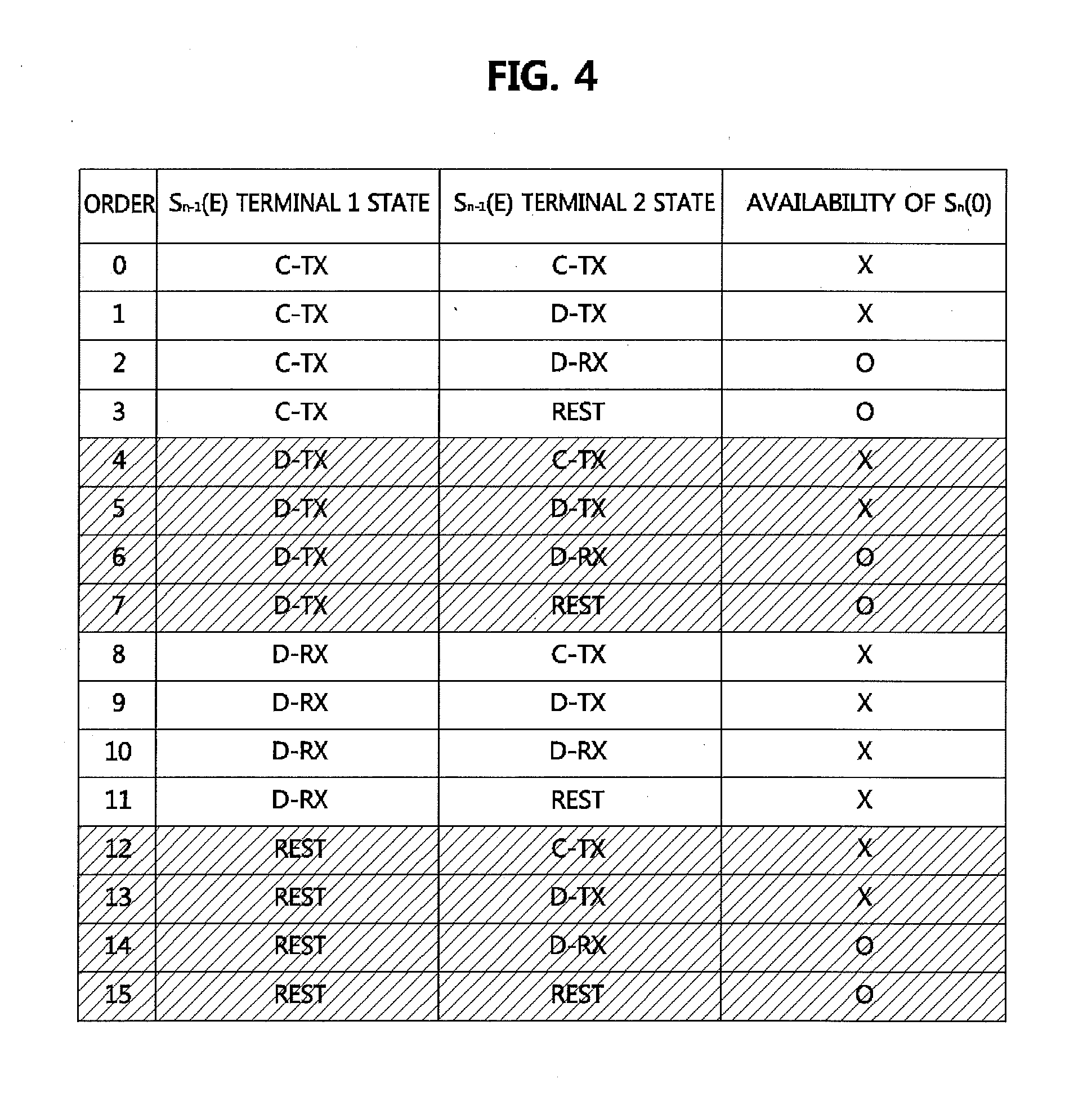
[0128](Case 1) Subframe (n−1) is not a Cell-Specific SRS Subframe

[0129]Case 1 corresponds to a case in which terminal 1 and terminal 2 are assumed to perform D2D communication with each other in subframe n, and subframe (n−1) is not one of cell-specific SRS subframes of terminal 1 and terminal 2.

[0130]FIG. 4 is a table showing whether transmission / reception for the first symbol of the subframe for D2D communication is possible according to a state of a terminal.

[0131]In the table of FIG. 4, a first column indicates order attached when transmission / reception for the first symbol of the subframe for D2D communication is possible. A second column indicates a state for the last symbol Sn−1(E) of subframe (n−1) of terminal 1 performing D2D transmission in subframe n. A third column shows a state for the last symbol Sn−1(E) of subframe (n−1) of terminal 2 performing D2D reception in subframe n. In this case, a fourth column in the table of FIG. 4 shows whether the first symbol Sn(0) of su...

case 2

[0134](Case 2) Subframe (n−1) is a Cell-Specific SRS Subframe

[0135]Case 2 corresponds to a case in which terminal 1 and terminal 2 are assumed to perform D2D communication with each other in subframe n and subframe (n−1) is one of cell-specific SRS subframes of the two terminals.

[0136]FIG. 5 is a table showing whether transmission / reception of the first symbol of the subframe for D2D communication is possible according to a state of terminal.

[0137]In the table of FIG. 5, a first column indicates order attached when transmission / reception for the first symbol of the subframe for D2D communication is possible. A second column indicates a state for the last symbol Sn−1(E) of subframe (n−1) of terminal 1 performing D2D transmission in subframe n. A third column shows a state for the last symbol Sn−1(E) of subframe (n−1) of terminal 2 performing D2D reception in subframe n. In this case, a fourth column in the table of FIG. 4 shows whether the first symbol Sn(0) of subframe n is availabl...

case 3

[0140](Case 3) Subframe n is not the Cell-Specific SRS Subframe

[0141]Case 3 corresponds to a case in which terminal 1 and terminal 2 are assumed to perform D2D communication with each other in subframe n, and subframe n is not one of cell-specific SRS subframes of terminal 1 and terminal 2

[0142]FIG. 6 is a table showing whether transmission / reception for the last symbol of the subframe for D2D communication is possible according to a state of a terminal.

[0143]In the table of FIG. 6, a first column indicates order attached when transmission / reception for the last symbol of the subframe for D2D communication is possible. A second column indicates a state for the first symbol Sn+1(0) of subframe (n+1) of terminal 1 performing D2D transmission in subframe n. A third column shows a state for the first symbol Sn+1(0) of subframe (n+1) of terminal 2 performing D2D reception in subframe n. In this case, a fourth column shows whether the last symbol Sn(E) of subframe n is available for D2D c...


PUM


Abstract

A method of transmitting and receiving a specific reference signal in single point transmission and multi-point transmission is disclosed. The specific reference signal transmission method includes determining specific reference signal transmission resources for at least one terminal targeted for transmission, and transmitting the specific reference signal using the determined transmission resources and notifying of information for a layer used by the terminal. The specific reference signal transmission method includes determining specific reference signal reception resources, receiving the information for the layer used by the terminal from a serving cell base station, and receiving the specific reference signal using the information for determined transmission resources and the layer. Therefore, the terminal can recognize a position and a sequence of the specific reference signal. Particularly, in the case of multi-user MIMO and cooperative scheduling, signal interference can be suppressed or removed using the specific reference signal of another terminal.

Description

CLAIM FOR PRIORITY[0001]This application claims priorities to Korean Patent Application Nos. 10-2012-0045195 filed on Apr. 30, 2012, 10-2012-0085066 filed on Aug. 3, 2012 and 10-2013-0047560 filed on Apr. 29, 2013 in the Korean Intellectual Property Office (KIPO), the entire contents of which are hereby incorporated by references.BACKGROUND[0002]1. Technical Field[0003]Example embodiments of the present invention relate to device-to-device communication, and more specifically, measurement of link channel state information for device-to-device communication, a method of modulating and demodulating a data channel, a method of mapping resources of the data channel, and design of a control channel.[0004]2. Related Art[0005]Device-to-device communication (hereinafter also referred to as D2D communication) means a communication scheme of performing direct data transmission and reception between two adjacent terminals, not via a base station. In other words, two terminals perform communica...

Claims


Application Information

Patent Timeline
Patent Type & Authority Applications(United States)
IPC IPC(8): H04W76/02
CPCH04W76/023H04L1/1861H04L5/0051H04L5/0053H04W76/14H04B7/24
Inventor SEO, BANG WONKO, YOUNG JONOH, TAE GYUNAHN, JAE YOUNG
Owner ELECTRONICS & TELECOMM RES INST
Why Eureka
Try Eureka