Optical fiber ribbon, method of manufacturing optical fiber ribbon, and optical cable

Active Publication Date: 2014-01-16
FUTONG GRP CO LTD 50 +1
View PDF1 Cites 32 Cited by
  • Summary
  • Abstract
  • Description
  • Claims
  • Application Information

AI Technical Summary

Benefits of technology

[0012]In an optical fiber ribbon of an embodiment of the present invention, a strain applied to the single-core coated optical fibers can be greatly reduced when the optical cable is bent, which enables the optical cable to have sufficient long-term reliability. Further, the collective connection is easy, which makes it possible to improve connection workability of the optical cable.
[0013]In a method of manufa

Problems solved by technology

However, in an optical cable in which these conventional rollable optical fiber ribbons are densely packed, a large strain is applied to the single-core coated optical fibers when the optical cable is bent.
Accordingly, it is not p

Method used


Image

  • Optical fiber ribbon, method of manufacturing optical fiber ribbon, and optical cable
  • Optical fiber ribbon, method of manufacturing optical fiber ribbon, and optical cable
  • Optical fiber ribbon, method of manufacturing optical fiber ribbon, and optical cable

Examples


Example

EXAMPLE

[0068]Next, examples of the present invention and comparative examples will be concretely described, but the present invention is not limited at all to the following examples.

Example

Example 1

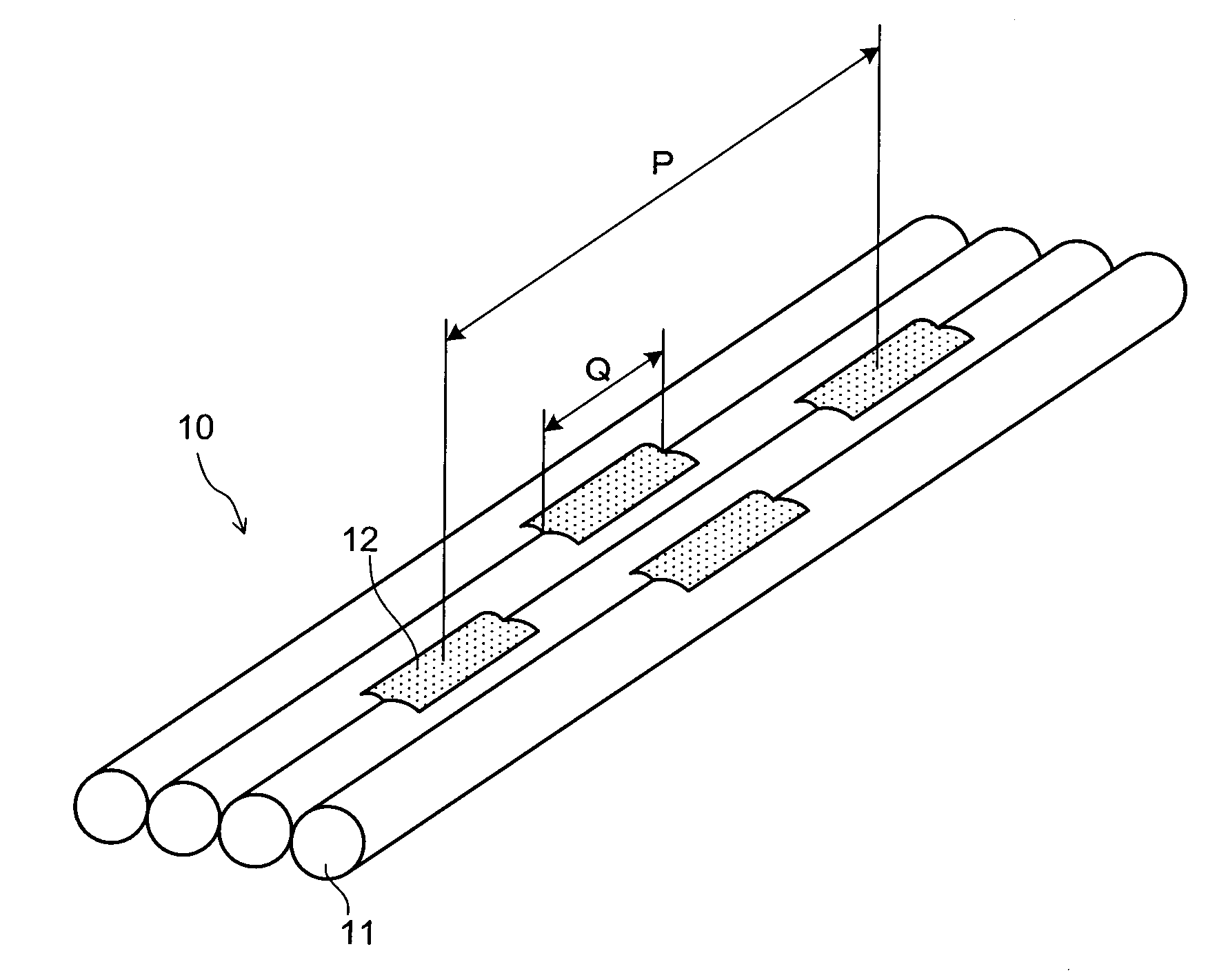
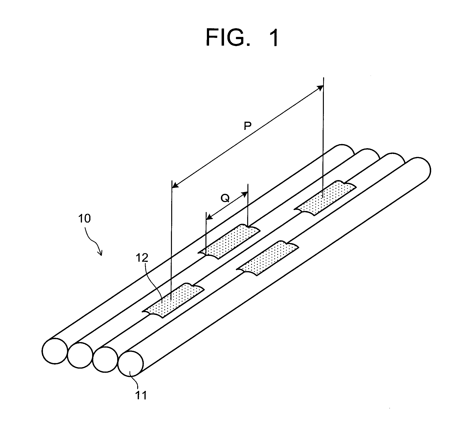
[0069]An optical fiber ribbon shown in FIG. 1 was fabricated in which a length Q of coupling parts each coupling only two adjacent single-core coated optical fibers and their arrangement interval P were 3 mm and 65 mm respectively. As the single-core coated optical fiber, used was a single-core coated optical fiber with a 250 μm outside diameter (D) in which a silica glass SM optical fiber with a 125 μm outside diameter was coated with a primary coating made of urethane acrylate-based ultraviolet curable resin whose Young's modulus at 23° C. was 5 MPa and a secondary coating made of urethane acrylate-based ultraviolet curable resin whose Young's modulus at 23° C. was about 700 MPa. Further, for forming the coupling parts, used was acrylic ultraviolet curable resin whose viscosity at 25° C. measured by a cone plate viscometer based on JIS K 6833 was 14000 mPa·s.

[0070]Next, these optical fiber ribbons were used to manufacture a 200-core optical cable shown in FIG. 6. The five...

Example

Example 2, Comparative Examples 1 to 7

[0074]Optical fiber ribbons were fabricated in the same manner as in the example 1 except that at least one of a length Q of coupling parts each coupling only two adjacent single-core coated optical fibers and their arrangement interval P was varied as shown in Table 1. Further, optical cables were fabricated by using the obtained optical fiber ribbons as in the example 1.

[0075]Regarding the above-described optical cables 1 obtained in the examples and the comparative examples, a strain characteristic when the optical cable was bent was examined and connection workability of the optical fiber ribbons was evaluated.

[0076]As for the strain characteristic when the optical cable was bent, the optical cable was bent, with a 120 mm radius, a 300 mm radius, and a 500 mm radius, and strains occurring in the single-core coated optical fibers at this time were measured, and their maximum value was found. The strains were measured by a high-resolution stra...


PUM


Abstract

There is provided an optical fiber ribbon capable of realizing, in an optical cable, sure reliability, a reduction in size and weight, higher density, and a further improvement in workability, a method of manufacturing the same, and an optical cable using such an optical fiber ribbon. An optical fiber ribbon 10 includes four single-core coated optical fibers 11 arranged in parallel on a same plane; and coupling parts 12 arranged at intervals in a length direction and a width direction, each coupling only adjacent two of the single-core coated optical fibers 11, wherein an interval P of the coupling parts 12 coupling the same two single-core coated optical fibers is not less than 20 mm nor more than 90 mm and a length Q of each of the coupling parts 12 is not less than 1 mm nor more than 10 mm.

Description

TECHNICAL FIELD[0001]The present invention relates to an optical fiber ribbon, a method of manufacturing an optical fiber ribbon, and an optical cable.BACKGROUND ART[0002]In accordance with the recent expansion of optical communication networks, not only sufficient reliability but also a further reduction in size and weight, higher density, and an improvement in workability have been required of optical cables.[0003]As an optical cable realizing a reduction in size and weight, higher density, and improved workability, one with so-called rollable optical fiber ribbons, for instance, has been known, in which only two adjacent fibers out of three single-core coated optical fibers or more arranged in parallel are bonded by each resin part, the resin parts are longer in length than non-resin parts, and the resin parts adjacent in a width direction are spaced apart from each (see, for example, References 1 and 2).[0004]Being small in bending anisotropy, such an rollable optical fiber ribb...

Claims


Application Information

Patent Timeline
IPC IPC(8): G02B6/44
CPCG02B6/4403G02B6/4405G02B6/04G02B6/44
Inventor TANABE, KENGOKANEKO, TAKAO
Owner FUTONG GRP CO LTD 50
Why Eureka
Try Eureka