
Communications apparatus

a technology of communication apparatus and equipment, applied in the field of communication equipment, can solve the problems of no reported easy method in terms of hardware or convenience to estimate (or compute) the loudness and duration of music, user of electronic devices may suffer from noise-induced deafness, no easy method in terms of convenience and hardware, etc., and achieve the effect of small form factor and not easily broken

Inactive Publication Date: 2014-01-16
ADVANCED ELECTROACOUSTICS PRIVATE
View PDF10 Cites 48 Cited by
  • Summary
  • Abstract
  • Description
  • Claims
  • Application Information

AI Technical Summary

Benefits of technology

The patent describes an intermediary communications device that allows easy measurement of the output of an electronic device, such as a music player in a smartphone. It is designed to be convenient, simple in hardware, and mechanically strong, with minimal power requirements. The device can wireless communicate with other electronic devices, such as a hearing aid or pacemaker, through the Internet. The device uses a resistor and a battery for power, and can also connect an external microphone for better sampling. The technical effect of this invention is to provide a simple yet effective solution for measuring the output of electronic devices and facilitating wireless communications between them.

Problems solved by technology

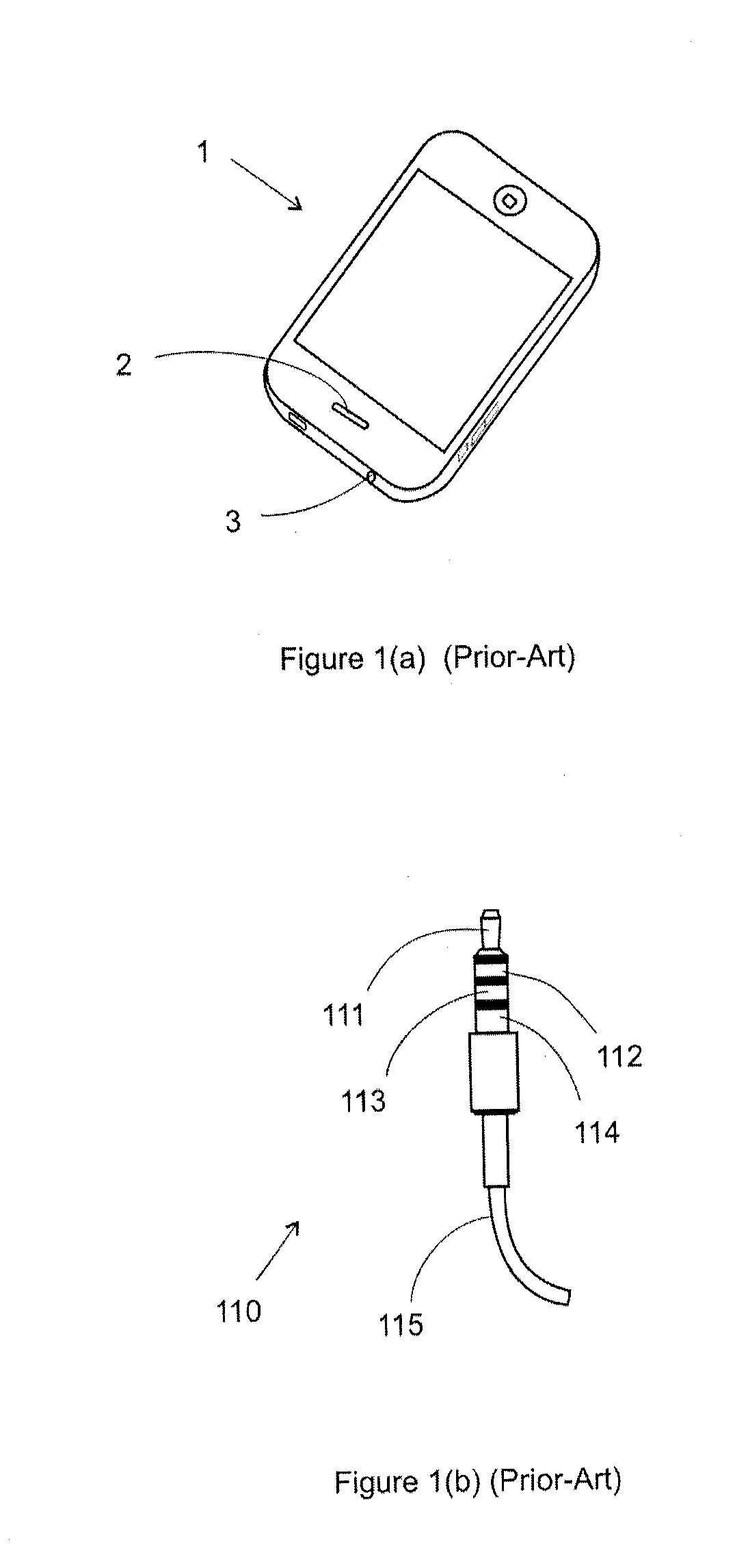
In such electronic devices, there is no reported easy method in terms of hardware or convenience to estimate (or compute) the loudness and duration of the music / sound exposed to the user of the music player who wears earphones connected to the earphone output of the music player.
When the noise dosage exceeds the stipulated safety limits, the user of the electronic device may suffer from noise induced deafness.
There is no easy method in terms of convenience and hardware because of one or more of the following reasons.
Second, the operating system of music players (e.g. in smartphones) does not allow other applications therein access to the output of its digital signal processor / digital-to-analog converter / power amplifier.
This lack of access renders the need for hardware external to the music player where the external hardware would need access the earphone output to monitor / measure its electronic signal output (and use the output / input transfer function from the acoustic output of the loudspeaker to its electronic input) or to directly measure the acoustical output of the loudspeaker.
Cumbersome / impractical prior-art inventions include US Patent 2009 / 0208024, US Patent No.
In short, there is no known method to exploit the microphone bias to make it convenient or to reduce the hardware to realize a means of ascertaining the output of the earphone and / or the
The limitation of only infrared is probably due to the desired application, and the use of the earphone output thereby disallowing the use of a earphone / headphone.
As this device protrudes out of the smartphone, it can be broken easily.
In short, the functionality is restricted and mechanically weak (easily broken).
The serious shortcoming of this prior-art method is that the magnetic field generated by the loudspeaker is very weak, requiring careful and difficult placement / alignment (require fiddling—trial and error to try to find a ‘sweet’ spot) of the loudspeaker (of the mobile phone) near the hearing aid.
In most cases, the magnetic induction remains weak, rendering the simplex transmission unsatisfactory, and the speech intelligibility poor.
The credit card reader protrudes out of the smartphone and is hence mechanically weak (easily broken).
This invention is hence limiting as it is not easily adapted to any phone, particularly smartphones.
This is hence not generally applicable nor convenient.
Further, the mechanical connection is weak (easily broken).
The cumbersomeness is largely due to the difficult attachment, large form factor and the electronics therein requiring an external battery.
In the aforesaid inventions and prior-art electronic devices with their associated comms apparatus, the application of the smartphone (and the like) remains limited and often cumbersome, and this is due to a number of reasons.
First, in the case of ascertaining noise dosage arising from the audio output of an electronic device, there is no easy means in terms of convenience or in terms of hardware and power source, rendering their realization in large form factor, hence commercially unacceptable.
Second, the power available from the microphone bias in the electronic device is very limited, typically <250 microamperes at <2V.
Third, in applications where the microphone input is already connected to a microphone, this input means is largely unavailable as a power source or as an input.
Fourth, when data is input into the microphone, the microphone input is not easily applicable as a power source.
Fifth, in applications where the earphone output of the electronic device (e.g. smartphone) is already connected to a loudspeaker of earphones (or headphones), this means as an output to the electronics in the comms apparatus is not readily available.
In short, prior-art comms apparatus inventions for measuring the earphone output of electronic devices (e.g. music players in smartphones) and for communications between a first electronic device (e.g. smartphone) and a second electronic device (e.g. hearing aid, pacemaker, etc) are cumbersome and limiting, or mechanically weak (easily broken).
Physically, they are often external devices (a separate entity), requiring an external power source, communications are limited (e.g. localized communications instead of more global communications (for example communications between a third electronic device (e.g. a hearing diagnostic system) at one end of the internet, a smartphone (first electronic device) at the other end of the internet, and communications between the smartphone and a hearing aid (second electronic device) via the comms apparatus)), and applicable only to specialized phones, etc.

Method used


Image

  • Communications apparatus
  • Communications apparatus
  • Communications apparatus

Examples


first embodiment

[0045]It is apparent that there are several unique advantages of the first embodiment and first preferred embodiment of the present invention, including no external power required for Comms Apparatus 51, the extreme simplicity of electronics in the Comms Apparatus 51 and its ensuing very small form factor. These uniqueness would provide a highly practical and commercially acceptable noise dosimeter.

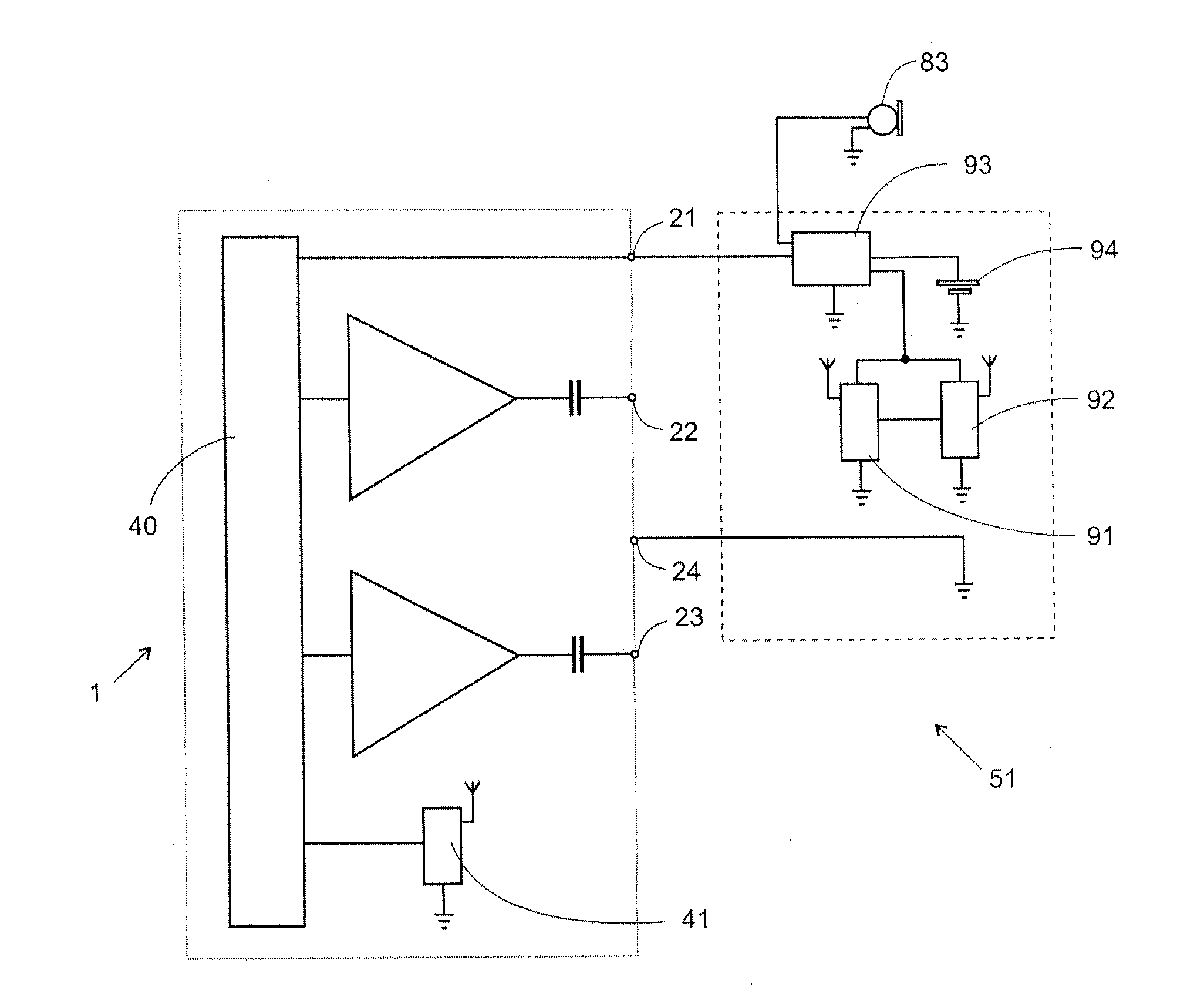
[0046]FIG. 3(c) depicts the further preferred first embodiment of the invention where power is now harvested from Microphone Input 21. Comms Apparatus 51 comprises Power Management 63 and Electronics 64. As before, the input to Loudspeaker 81 and Loudspeaker 82 are respectively Left Channel Output 22 and Right Channel Output 23 of Mobile Phone 1. Electronics 64 derives its power from Microphone Input 21 via Power Management 63. Depending on the power requirements of the electronics in Electronics 64, Power Management 63 may be as simple as not requiring any electronics, a capacitor or as ...

second embodiment

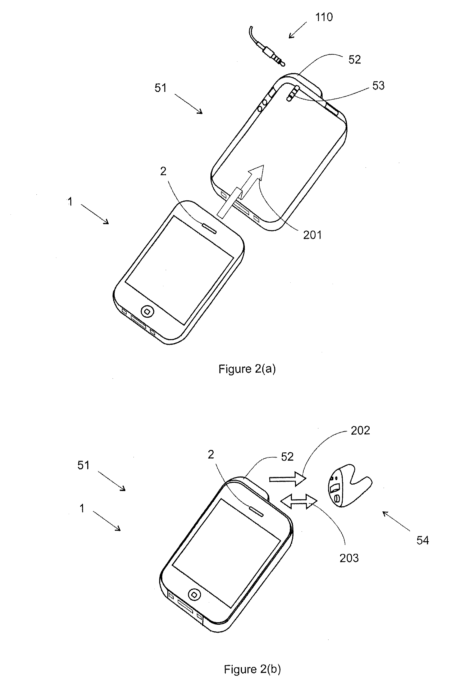
[0056]FIG. 4(a) depicts the invention where an application is short-range simplex communications between first electronic device Mobile Phone 1 and second electronic device via Comms Apparatus 51. In FIG. 2(b), the second electronic device is Hearing Aid 54, and in other applications, the second electronic device may be a pacemaker, etc. In one example application, first electronic device Mobile Phone 1 may be able to transmit data to second electronic device, including for simplex communication, for control, audio data communication, etc, via Comms Apparatus 51.

[0057]In FIG. 4(a), Comms Apparatus 51 comprises Transmitter 71 whose input is Left Channel Output 22 of first electronic device Mobile Phone 1. Transmitter 71 is a passive transmitter, thereby not requiring power, for example a telecoil (also known as T-coil) where the modality of transmission is magnetic induction; also known as loop system. In this application, second electronic device (e.g. Hearing Aid 54 in FIG. 2(b)) w...

third embodiment

[0076]Further, if Mobile Phone 1 is internet enabled, a third electronic device at the other end of the internet can now communicate (full-duplex) with the second electronic device. Consider the use of this third embodiment of the invention for a revolutionary hearing aid application (and other like applications) where the third electronic device at the far end of the internet connection is a hearing aid diagnostic system, first electronic Mobile Phone 1 is at the near end of the internet, and Hearing Aid 54 being the second electronic device. Mobile Phone 1 and Comms Apparatus 51 are now collectively the intermediary communications devices between the second electronic device (e.g. Hearing Aid 54) and the third electronic device (hearing aid diagnostic system). The manufacturer of a hearing aid by means of the hearing aid diagnostic system may now remotely diagnose (and / or program, collect data, etc.) the hearing aid.

[0077]The overall communications system is as follows. Third elec...


PUM


Abstract

A versatile communications (comms) apparatus to provide a means to measure the audio (earphone) output of an electronic device (e.g. a music player in a smartphone), and / or to provide a means for wireless communications between a first electronic device (e.g. a smartphone) and a second electronic device (e.g. a hearing aid, pacemaker, etc). In some embodiments, the comms apparatus does not need power and in other embodiments, its power may be harvested from the first electronic device, or drawn from a battery that may be recharged by harvesting means or charged directly. The first electronic device typically includes an audio (earphone) output, a microphone input (with a voltage bias), a long-range communications transceiver (e.g. GSM), and where pertinent, a short-range transceiver (e.g. Bluetooth) and is internet enabled. In one embodiment, the comms apparatus provides a means where the audio output (earphone) of the electronic device is sampled by its microphone input, or by electronics in the comms apparatus. In other embodiments, the comms apparatus is an intermediary communications device between the first electronic device and the second electronic device. The communications therein may be simplex and / or duplex, via either the audio output (earphone), microphone input, short-range transceiver, and / or a combination thereof. The communications data (via the comms apparatus) may be transmitted elsewhere, including via the internet by means of the internet enabled electronic device.

Description

FIELD OF THE INVENTION[0001]This invention relates to a communications apparatus to provide a means to measure the audio output of an electronic device (e.g. a portable music player in a smartphone); and / or to provide a means for wireless communications between a first electronic device (e.g. a smartphone) and a second electronic device (e.g. a hearing aid, pacemaker, and the like), and communications may be communicated elsewhere via the internet.BACKGROUND OF THE INVENTION[0002]Many electronic devices, including portable music players, have a microphone input that is typically biased to around 2.3V. The microphone input is typically connected to an external microphone or it may be used as a power source (from its bias); for simplicity, ‘microphone input’ and ‘microphone bias’ will be used interchangeably. In these electronic devices, the microphone and the earphone operate independently. In the case of music players, when music is played (the output is at the earphone output), the...

Claims


Application Information

Patent Timeline
Patent Type & Authority Applications(United States)
IPC IPC(8): H04B15/00H04M1/72412H04M1/7246H04M1/72478
CPCH04B15/00H04R25/554H04R29/001H02J7/32H04M1/04H04R2227/003H04R2420/07H04R27/00Y02B40/00H04M1/72412H04M1/7246H04M1/72478
Inventor CHANG, JOSEPH SYLVESTERLEE, CHAI LUNGGE, TONG
Owner ADVANCED ELECTROACOUSTICS PRIVATE
Learn More