Magnetic Marker for Surgical Localization

Inactive Publication Date: 2014-01-16
ENDOMAGNETICS LTD
View PDF11 Cites 44 Cited by
  • Summary
  • Abstract
  • Description
  • Claims
  • Application Information

AI Technical Summary

Benefits of technology

[0045]A further advantage of the present invention is that iron oxide magnetic nanoparticles are visible by most of the most common medical imaging methods. Iron oxide MNPS are known in the art to be visible under MRI and they have been used as contrast enhancement agents. MNPs also are visible under the various X-ray based imaging modalities. A number of imaging techniques are under development which offer the possibility of real-time imaging in the operating room during surgery; for example, photo-acoustic imaging, magnetic particle imaging, magneto-acoustic imaging, and magneto-photo-acoustic imaging. Iron oxide MNPs are also potentially visible using all these imaging techniques.
[0046]To enhance the visibility of the marker under X-ray, an additional X-ray visible element may be added to the marker. This may be a solid metal element, for example, a small piece of titanium or stainless steel or an X-ray visible ceramic such as zirconia. Various forms and shapes are suitable including clips, springs, coils, wires, cylinders, rings and elements formed from sheet material. The element may be embedded in the marker or delivered with the marker. Preferably, the element is associated with the marker so that it marks the desired site and is not subject to migration. Where appropriate, the element is coated to enhance biocompatibility.
[0047]X-ray visibility can also be achieved by the addition of radiopaque compounds, for example compounds containing barium or iodine compounds, or other heavy elements. This approach is advantageous for liquid or gel markers as the radiopaque compounds can also be formulated in this form.
[0048]Iron oxide MNPs are not typically v

Problems solved by technology

First, it involves two separate procedures, and can present logistical and scheduling difficulties between radiology and surgery departments.
Second, the positioning of the guidewire may not be optimal for achieving the desired cosmetic result in the subsequent surgery.
Third, the hook wire can migrate away from the site of the lesion or become displaced during mammography or moving the patient.
Fourth, the insertion of the wire can be painful for patients and finally, the risk of infection means that surgery usually needs to take p

Method used


Image

  • Magnetic Marker for Surgical Localization
  • Magnetic Marker for Surgical Localization
  • Magnetic Marker for Surgical Localization

Examples


Example

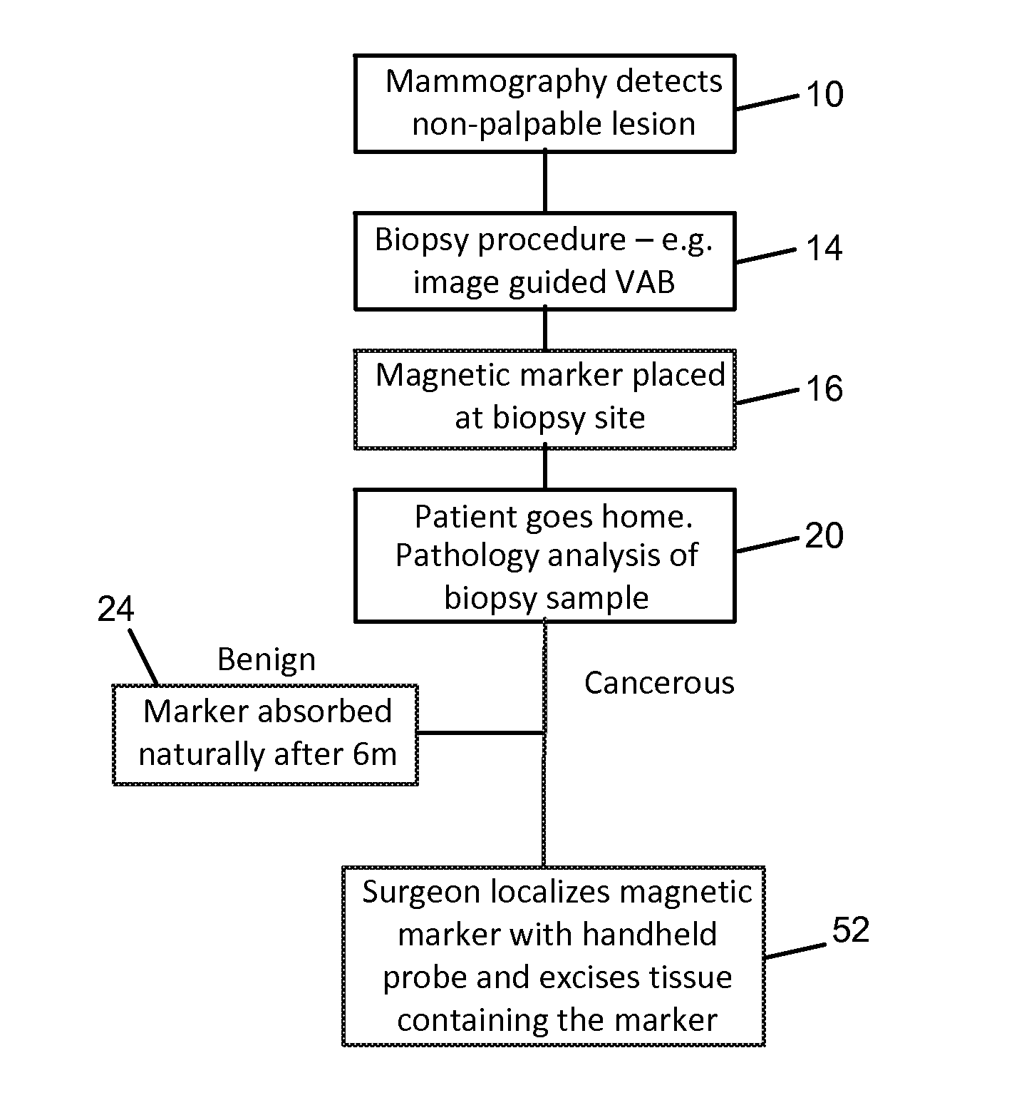
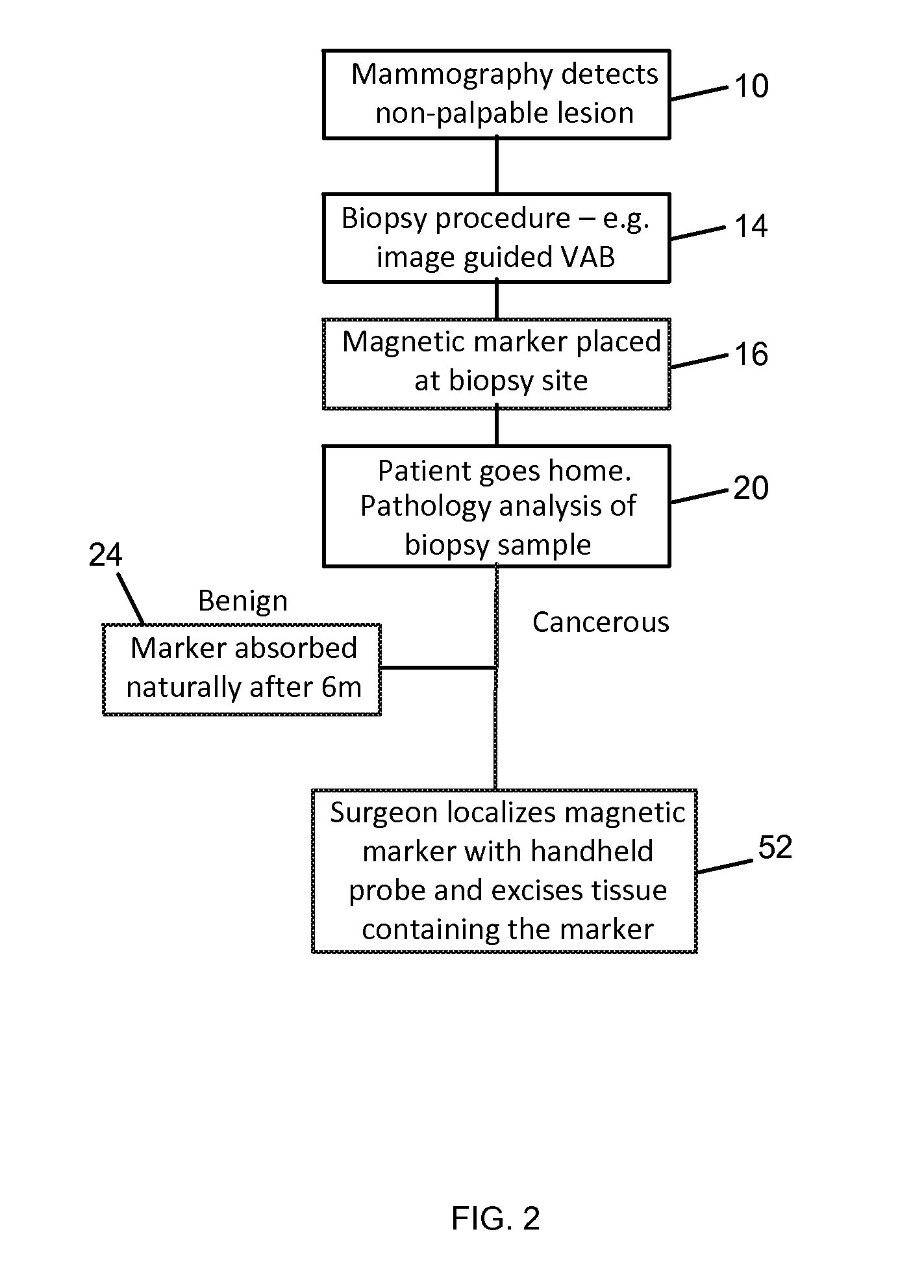
[0025]The present invention relates to a marker that can be positioned following a biopsy procedure, remains visible under a range of imaging modalities for a period of months in order to allow re-localization in cases where patients receive a course of neo-adjuvant chemotherapy before removal of the tumor, and is absorbed by the body after a number of months. In one embodiment, the marker is absorbed after 6 months.

[0026]The present invention discloses a marker for marking the site of the lesion with a magnetic material, for example a material containing superparamagnetic nanoparticles, which can be subsequently detected and localized interoperatively by using a handheld magnetometer. The marker may be placed at the site of the lesion at the time of the initial biopsy. In the case where the biopsy sample indicates that the lesion is benign, the marker remains in the breast and is absorbed over a period of time, in one embodiment, six months.

[0027]If the biopsy shows that the lesion...


PUM


Abstract

A method and apparatus for preparing tissue of interest in a patient for possible excision by surgery. In one embodiment, the method comprises the steps of: removing a biopsy sample from the tissue of interest; placing a magnetic marker at the biopsy site; performing a pathology analysis of the biopsy sample; and if the pathology analysis indicates that the tissue of interest should be removed, locating the tissue for surgery using a magnetic detection probe. In one embodiment, the marker comprises magnetic nanoparticles in a bioabsorbable matrix. A system for preparing tissue of interest in a patient for possible excision by surgery. In one embodiment, the system includes a magnetic marker and magnetic detection probe system.

Description

CROSS-REFERENCE TO RELATED APPLICATION[0001]This application claims priority to and the benefit of U.S. Provisional Patent Application No. 61 / 672,048, filed Jul. 16, 2012, the entire disclosure of which is hereby incorporated by reference herein, in its entirety and for all purposes.FIELD OF THE INVENTION[0002]The invention relates in general to surgical devices and more specifically to devices that aid in locating a lesion for surgical excision.BACKGROUND OF THE INVENTION[0003]With the increasing prevalence of mammography screening programs, the majority of breast cancers are detected as small, non-palpable (or occult) lesions, that are amenable to breast conserving treatment. Accurate localization of non-palpable breast cancers is key to allowing surgical removal of the complete tumor with adequate margins. If the tumor is not completely excised, patients need to undergo a further operation to remove any remaining cancerous tissue. Accurate localization also helps to avoid excisio...

Claims


Application Information

Patent Timeline
IPC IPC(8): A61B5/06A61B10/02
CPCA61B5/062A61B10/02A61B5/06A61B5/4312A61B90/39A61B2090/3908A61B2090/3954
Inventor HARMER, QUENTIN JOHNMAYES, ERICPANKHURST, QUENTIN ANDREWSHAWCROSS, ANDREW
Owner ENDOMAGNETICS LTD
Why Eureka
Try Eureka