
Motor controlling circuit, motor driving device and method of driving motor

Inactive Publication Date: 2014-01-30
SAMSUNG ELECTRO MECHANICS CO LTD
View PDF2 Cites 4 Cited by
  • Summary
  • Abstract
  • Description
  • Claims
  • Application Information

AI Technical Summary

Benefits of technology

This patent describes a motor controlling circuit, device, and method that can efficiently generate signals to control a motor by comparing impulse signals with a preset time. It also includes a feature to prevent the motor from rotating in reverse by identifying impulse or noise signals during the process of stabilizing a hall signal.

Problems solved by technology

Since driving of the motor is controlled according to the hall signal, in the case in which noise is generated in the hall signal, erroneous motor controlling signals may be generated, such that the motor may rotate in reverse.
Here, in controlling the driving of the motor, in the case in which the motor controlling signals are generated by detecting both of the rising and falling edges of each impulse signal generated before a high level is stabilized, motor driving efficiency may be deteriorated.

Method used


Image

  • Motor controlling circuit, motor driving device and method of driving motor
  • Motor controlling circuit, motor driving device and method of driving motor
  • Motor controlling circuit, motor driving device and method of driving motor

Examples


Embodiment Construction

[0029]Hereinafter, embodiments of the present invention will be described in detail with reference to the accompanying drawings. The invention may, however, be embodied in many different forms and should not be construed as being limited to the embodiments set forth herein. Rather, these embodiments are provided so that this disclosure will be thorough and complete, and will fully convey the scope of the invention to those skilled in the art. In the drawings, the shapes and dimensions of elements may be exaggerated for clarity, and the same reference numerals will be used throughout to designate the same or like elements.

[0030]Hereinafter, embodiments of the present invention will be described in detail with reference to the accompanying drawings so that those skilled in the art may easily practice the present invention.

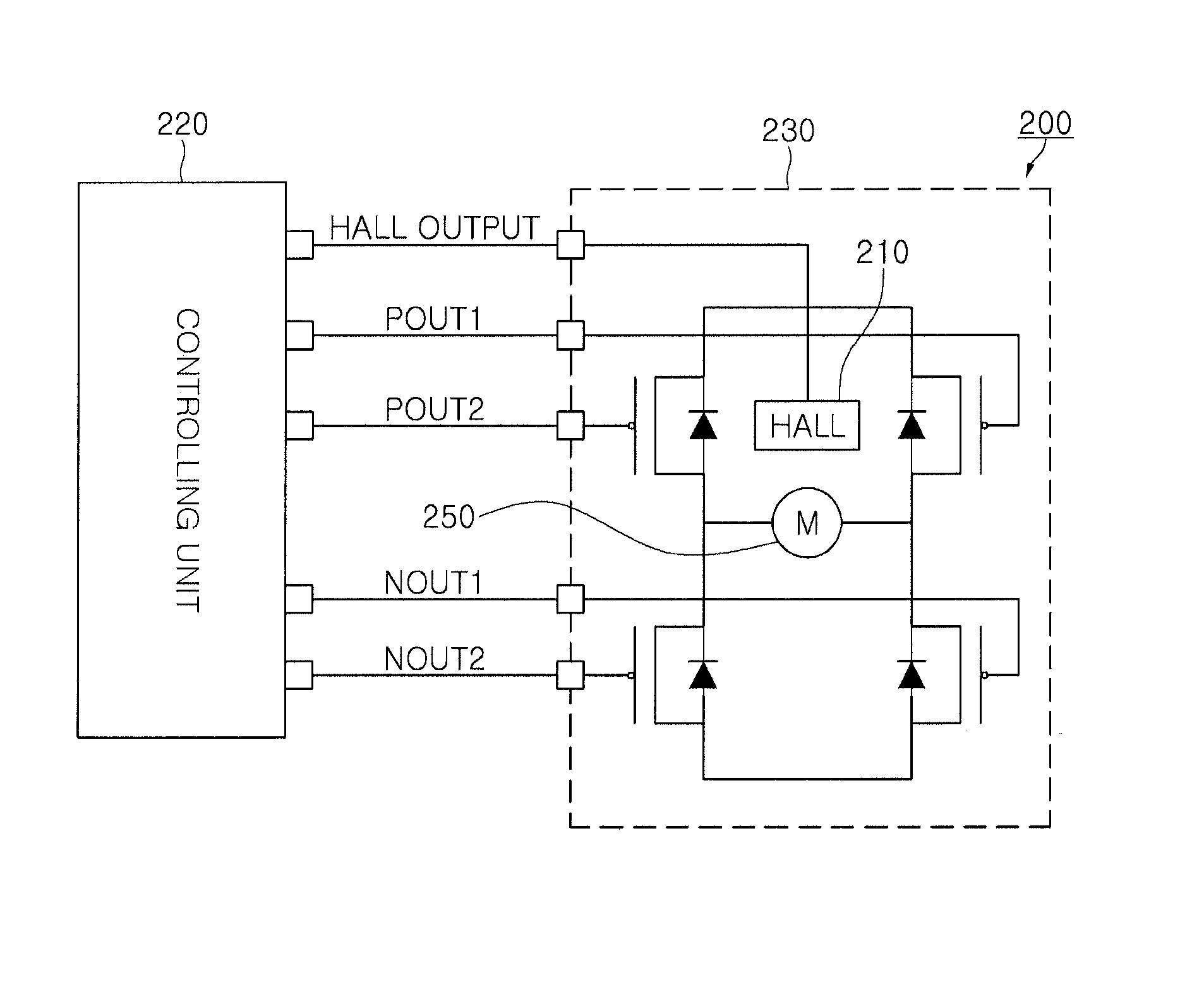
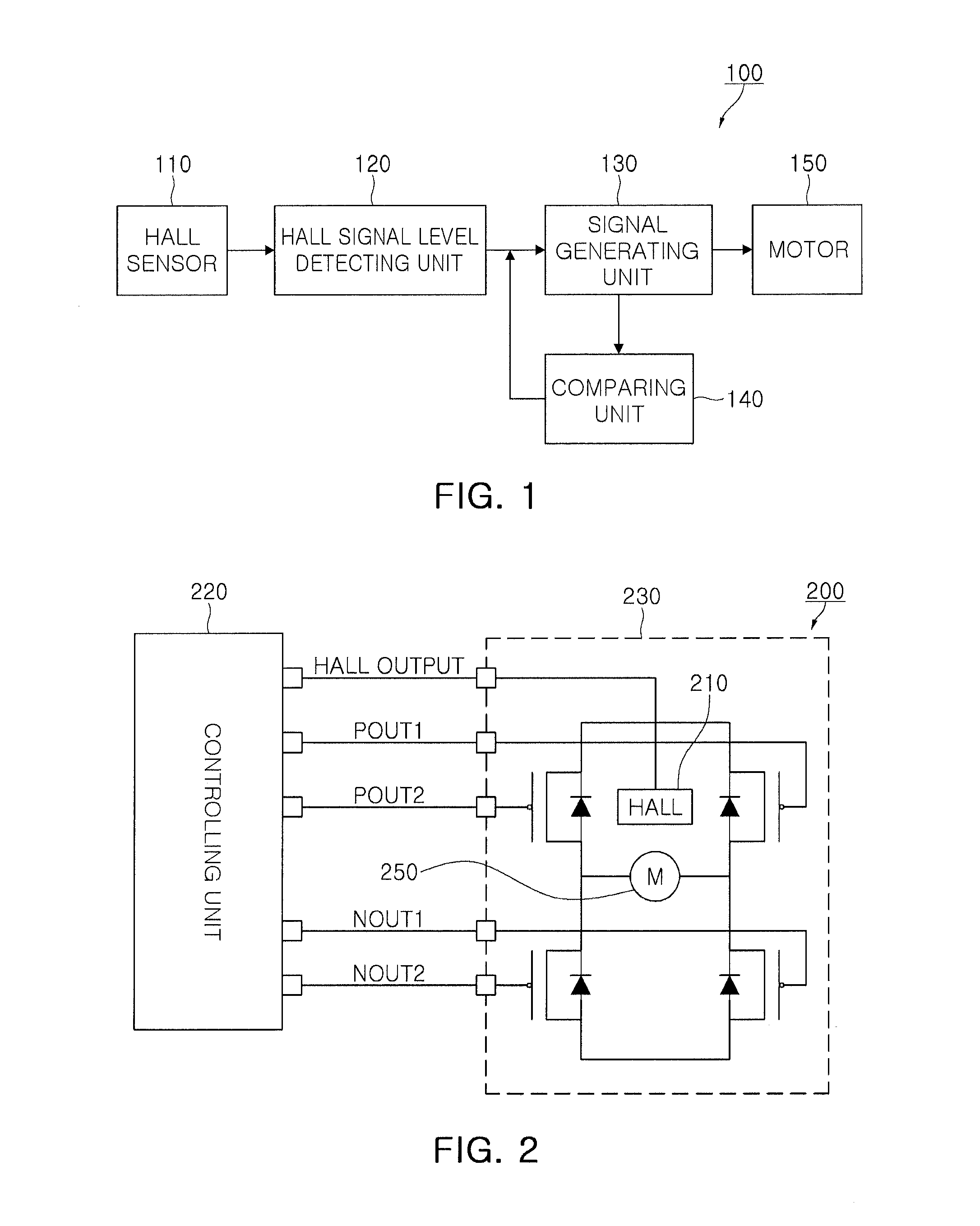
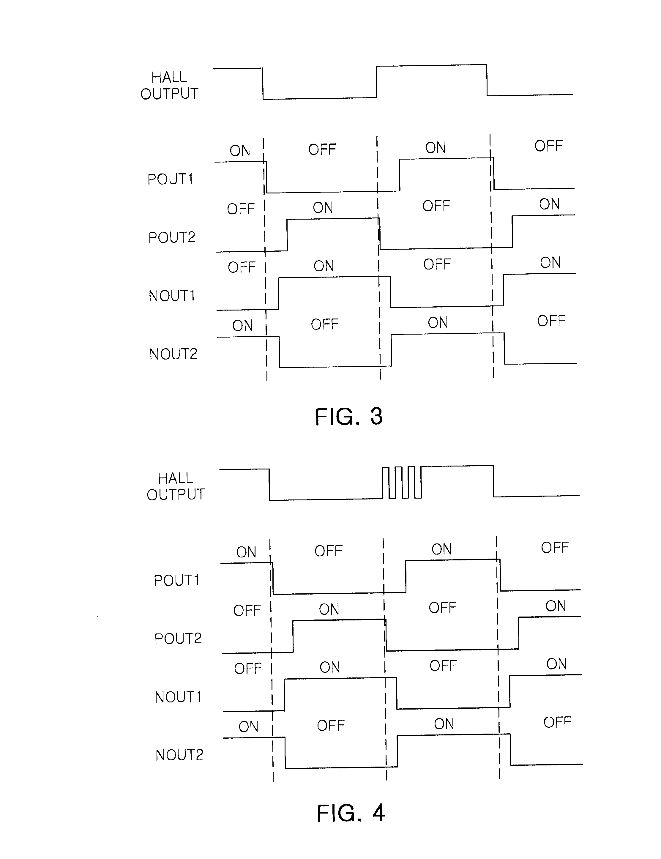
[0031]FIG. 1 is a block diagram schematically illustrating a motor controlling circuit 100 according to an embodiment of the present invention.

[0032]Referring to FIG...


PUM


Abstract

There is provided a motor controlling circuit including: a hall signal level detecting unit detecting a hall signal from a hall sensor; and a signal generating unit sensing a change in a level of the hall signal to generate a motor controlling signal according to the change in the level of the hall signal, wherein the signal generating unit determines that the hall signal is maintained at a high level in a case in which a high level maintaining time of the hall signal is equal to or shorter than a preset time.

Description

CROSS-REFERENCE TO RELATED APPLICATIONS[0001]This application claims the priority of Korean Patent Application No. 10-2012-0080762 filed on Jul. 24, 2012, in the Korean Intellectual Property Office, the disclosure of which is incorporated herein by reference.BACKGROUND OF THE INVENTION[0002]1. Field of the Invention[0003]The present invention relates to a motor controlling circuit, a motor driving device, and a method of driving a motor.[0004]2. Description of the Related Art[0005]A brushless direct current (BLDC) motor generally refers to a DC motor in which a function of conducting current or adjusting a current direction is adjusted by using a non-contact position detector and a semiconductor device rather than using a mechanical contact such as a brush, a commutator, or the like, in the DC motor.[0006]Generally, a speed of a motor, of which a speed is controllable, may be controlled by adjusting a duty value of a pulse width modulation (PWM) signal. The duty value of the pulse w...

Claims


Application Information

Patent Timeline
IPC IPC(8): H02P7/00H02P6/06H02P6/08H02P6/26
CPCH02P6/17H02P7/00H02P6/085H02P6/16H02P2203/03H02K29/08
Inventor GU, BON YOUNG
Owner SAMSUNG ELECTRO MECHANICS CO LTD
Learn More