Display device and control method for display device

a display device and control method technology, applied in the field of display devices, can solve the problems of (i) a large circuit, (ii) no luminance improvement, and (iii) no luminance improvement, and achieve the effect of preventing the display quality from decreasing

Active Publication Date: 2014-01-30
SHARP KK
View PDF0 Cites 20 Cited by
  • Summary
  • Abstract
  • Description
  • Claims
  • Application Information

AI Technical Summary

Benefits of technology

[0031]A method of the present invention for controlling a display device is a method for controlling a display device that (i) converts an input image including pixels having a first predetermined number of reference colors into a converted image including pixels having a second predetermined number of reference colors, the second predetermined number being larger than the first predetermined number, and that (ii) displays the converted image, the method including the steps of: (a) converting a luminance of the input image into a luminance of the converted image on a basis of a set value during the conversion of the input image into the converted image; (b) detecting, while the converting means is sequentially receiving input images that are substantially identical to each other, whether converted images corresponding to the respective input images have an oscillating luminance; and (c) fixing the luminance of the converted image in a case where the step (b) has detected that the converted images have an oscillating luminance.
[0033]As described above, a display device of the present invention is a display device that converts (i) an input image including pixels having a first predetermined number of reference colors into (ii) a converted image including pixels having a second predetermined number of reference colors, the second predetermined number being larger than the first predetermined number, and that displays the converted image, the display device including: converting means for converting a luminance of the input image into a luminance of the converted image on a basis of a set value during the conversion of the input image into the converted image; luminance oscillation detecting means for detecting, while the converting means is sequentially receiving input images that are substantially identical to each other, whether converted images corresponding to the respective input images have an oscillating luminance; and luminance fixing means for fixing the luminance of the converted image in a case where the luminance oscillation detecting means has detected that the converted images have an oscillating luminance.
[0035]The above arrangements each make it possible to advantageously prevent the display quality from decreasing as a result of oscillation of the luminance of a display image.

Problems solved by technology

This indicates that the technique of Patent Literature 1 can maintain chroma, but cannot improve luminance sufficiently.
In addition, converting R, G, and B input signals into R, G, B, and W signals and then further converting the R, G, B, and W signals into signals of R′, G′, B′, and W′ forces a driving circuit to internally carry out arithmetic processing in an even larger amount, resulting in (i) the circuit being overly large and (ii) a cost increase.
The above method inevitably causes at least one of R, G, and B outputs to be 0 if W is not nonlinearly processed.
During a white or gray display in particular, Rout=Gout=Bout=0 and W=min(Rin, Gin, Bin), which leads to no luminance improvement and to significant chroma decrease.
Nonlinearly processing W into W′ may alleviate the problem of chroma decrease, but still fails to improve luminance because carrying out nonlinear processing does not mean carrying out luminance expansion with respect to input signals.
The conventional technique disclosed in Patent Literature 3, however, problematically decreases the quality of a display image.
Specifically, the above conventional technique poses the following problems: First, the conventional technique carries out no luminance expansion with respect to primary colors.
Thus, in the case where a primary color and white are adjacent to each other, the primary color is seen as having chroma decrease, thereby decreasing the quality of a display image.
This leads to the presence of a pattern at which a video image is seen unnaturally, thereby decreasing the quality of a display image.
As described above, the respective techniques of Patent Literatures 1 to 3 are each problematic in that it cannot improve luminance while maintaining the hues of a video image and decreases the quality of a display image when determining color signals of R, G, B, and W from color signals of R, G, and B.

Method used


Image

  • Display device and control method for display device
  • Display device and control method for display device
  • Display device and control method for display device

Examples


embodiment 1

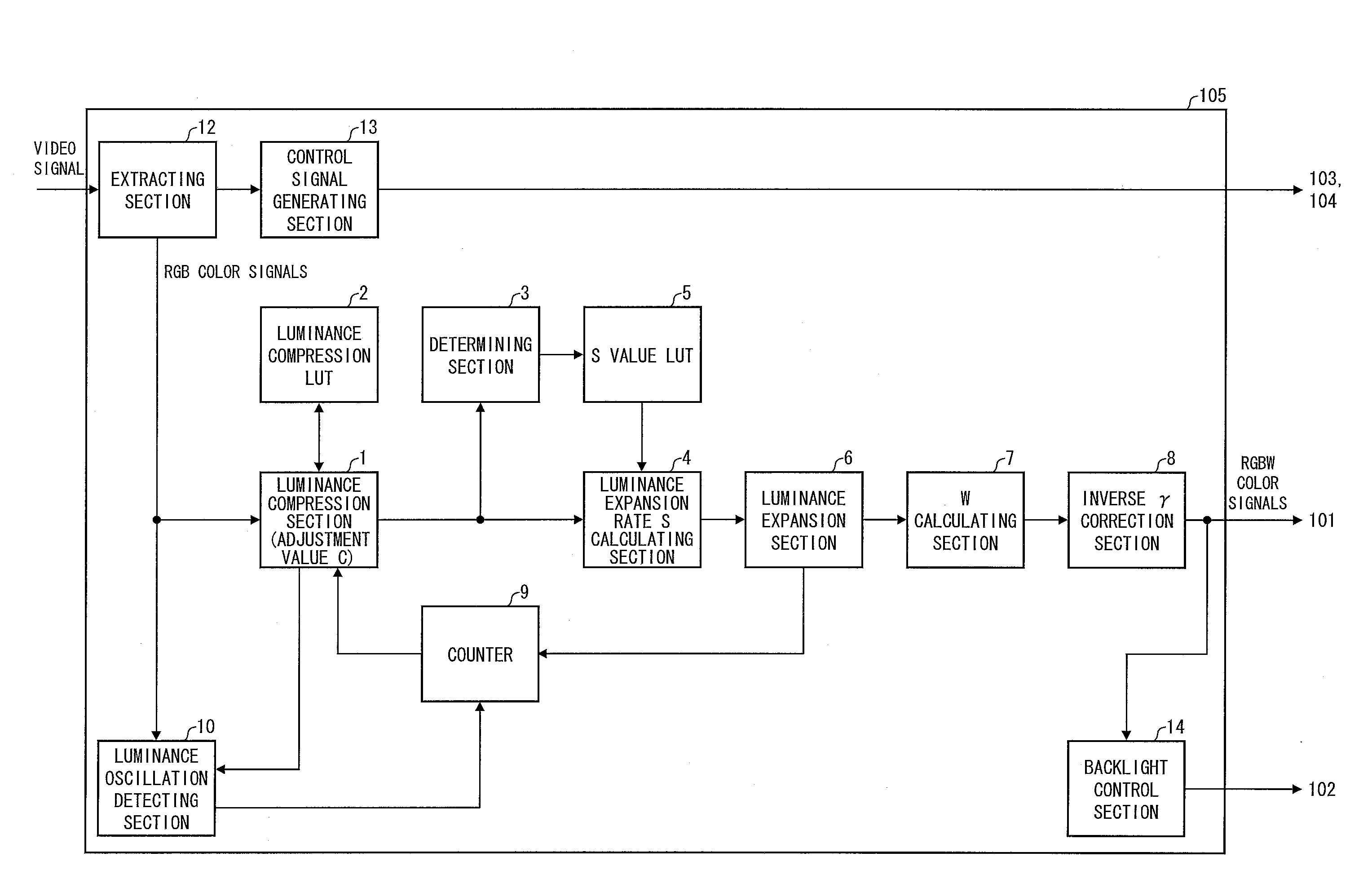
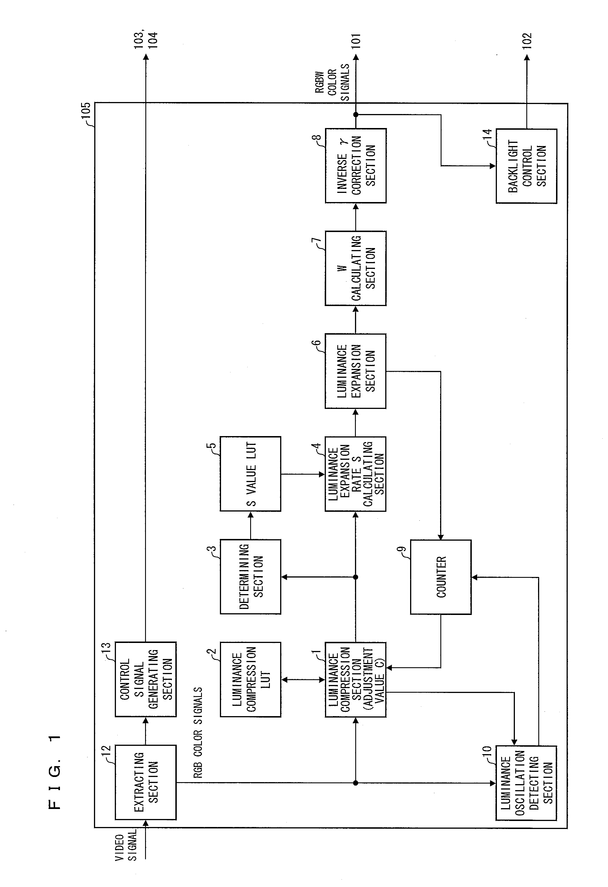
[0046]The description below deals with one embodiment of a liquid crystal display device as a display device of the present invention with reference to FIGS. 1 through 6.

[0047](Arrangement Description)

[0048]The liquid crystal display device of the present embodiment is arranged as a liquid crystal display device capable of carrying out high-resolution display, for example, an active matrix liquid crystal display device including thin film transistors (hereinafter referred to as “TFTs”) as switching elements.

[0049]The liquid crystal display device of the present embodiment is further arranged as a liquid crystal display device that converts (i) an input image including pixels having a first predetermined number of reference colors (in the present embodiment, the three colors of R [red], G [green], and B [blue]) into (ii) a converted image including pixels having a second predetermined number of reference colors (in the present embodiment, the four colors of R [red], G [green], B [blu...

embodiment 2

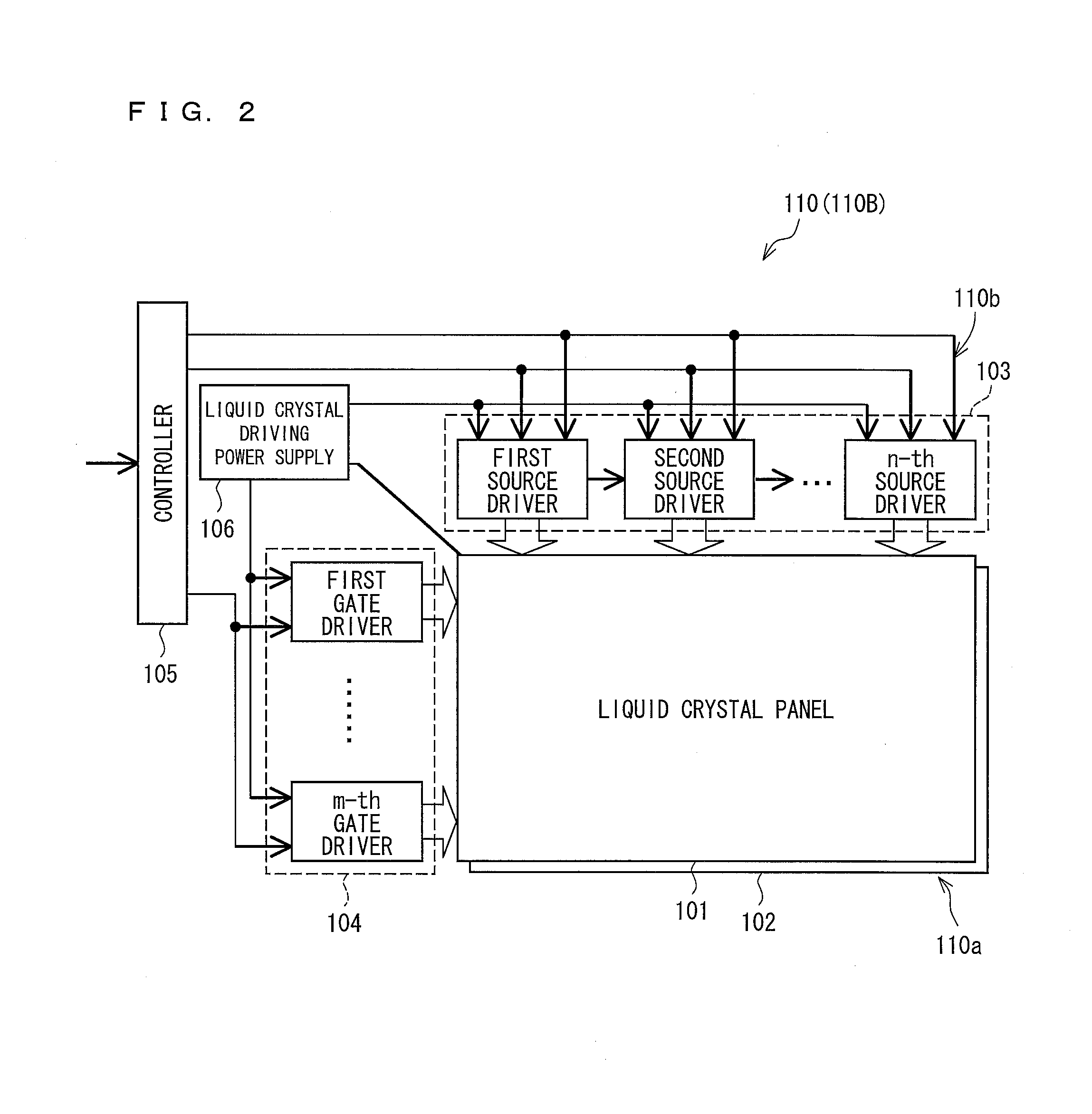
[0187]The present embodiment describes a liquid crystal display device 110B that is identical in arrangement to the liquid crystal display device of Embodiment 1 except that the liquid crystal display device 110B includes a backlight control section 14B and a luminance oscillation detecting section 10B each of which carries out processing different from that carried out by its corresponding member in Embodiment 1. The description below deals in detail with the present embodiment with reference to FIG. 8. The description below assigns, to any constituent element of the present embodiment which constituent element is identical to a corresponding constituent element of Embodiment 1, a reference numeral identical to that assigned to the corresponding constituent element, and does not deal with such identical constituent elements. The description below mainly deals with constituent elements of the present embodiment that are not included in Embodiment 1.

[0188]The backlight control sectio...


PUM


Abstract

Disclosed is a display device that (i) converts an input image formed of R, G, and B into a converted image formed of R, G, B, and W to display the converted image and that (ii) compresses the luminance of an input image for the subsequent frame on the basis of an adjustment value C which is corrected in correspondence with the number of, among all pixels in a converted image for the current frame, pixels in a state of luminance saturation and that then converts the input image into a converted image, the display device including a luminance oscillation detecting section (10) for detecting, while input images identical to each other are being inputted each as the above input image, whether converted images corresponding to the respective input images have an oscillating luminance, the display device, in the case where the luminance oscillation detecting section (10) has detected that the converted images have an oscillating luminance, stopping correction of the adjustment value C to fix the adjustment value C to a certain value, thereby preventing the converted images from having an oscillating luminance as a result of oscillation of the adjustment value C.

Description

TECHNICAL FIELD[0001]The present invention relates to a display device that (i) converts an input image including pixels having a first predetermined number of reference colors (for example, R, G, and B) into a converted image including pixels having a second predetermined number of reference colors (for example, R, G, B, and W), the second predetermined number being larger than the first predetermined number, and that (ii) displays the converted image.BACKGROUND ART[0002]A color liquid crystal display has conventionally included normally three pixels (picture elements) of R, G, and B in one (1) dot (pixel). Recent years have witnessed, however, a proposal of a color liquid crystal display that additionally includes a white (W) picture element for improved luminance, the color liquid crystal display thus including a total of four picture elements of R, G, B, and W in one (1) dot. This RGBW color liquid crystal display is advantageous in terms of luminance improvement, but tends to h...

Claims


Application Information

Patent Timeline
Patent Type & Authority Applications(United States)
IPC IPC(8): G09G3/36G09G3/20
CPCG09G3/2003G09G3/36G09G2300/0452G09G2320/0242G09G2340/06G09G2360/16G09G3/3406G09G5/04G09G5/06G09G3/3648G09G2320/0276G09G2340/02
Inventor TAKAHASHI, KOHZOHNAKANO, TAKETOSHIYAMATO, ASAHIINADA, KENKOBAYASHI, FUMIYUKIYANAGI, TOSHIHIRO
Owner SHARP KK
Why Eureka
Try Eureka