Optical disk device and method for controlling the same

Active Publication Date: 2014-01-30
PANASONIC SEMICON SOLUTIONS CO LTD
View PDF5 Cites 0 Cited by
  • Summary
  • Abstract
  • Description
  • Claims
  • Application Information

AI Technical Summary

Benefits of technology

The patent describes a method for correcting changes in the tilting (AC tilt) of an optical disk during storage and playback. The method uses a value that is obtained by averaging the shifting of the lens in a specific radial direction. This average value is used to ensure stability of the AC tilt correction, even if there are any disturbances during storage or playback. The method always uses the most recent lens shift amounts, which ensures that the AC tilt correction is able to adapt to changes in the optical disk. Overall, this method helps to improve the accuracy and reliability of AC tilt correction in optical disk storage and playback.

Problems solved by technology

The AC tilt leads to a decrease in signal quality during recording and reproduction of information to and from the optical disk.
However, the increase in the rigidity leads to a decrease in drive sensitivity and therefore to an increase in heat generation and power consumption.
However, the increase in weight of the objective lens leads to a decrease in responsiveness of the objective lens.
The technique of Japanese Patent Publication No. 2008-282439 has difficulty in ensuring the stability of AC tilt correction.
Specifically, when the optical pickup passes a defective portion of an optical disk which is called black dot out (BDO), focus position information and tracking position information cannot be accurately extracted.
As a result, an error occurs in the amount of tilt correction drive.
Therefore, the necessity of calculation of the equation of motion leads to an increase in cost of the optical disk device.
The technique of International Publication WO2008 / 149557 has difficulty in ensuring the following capability of AC tilt correction.
While the tracking control is stopped, at least one of reproduction and recording of information from and to an optical disk is not allowed, leading to an increase in the time required to activate the optical disk device.

Method used


Image

  • Optical disk device and method for controlling the same
  • Optical disk device and method for controlling the same
  • Optical disk device and method for controlling the same

Examples


first embodiment

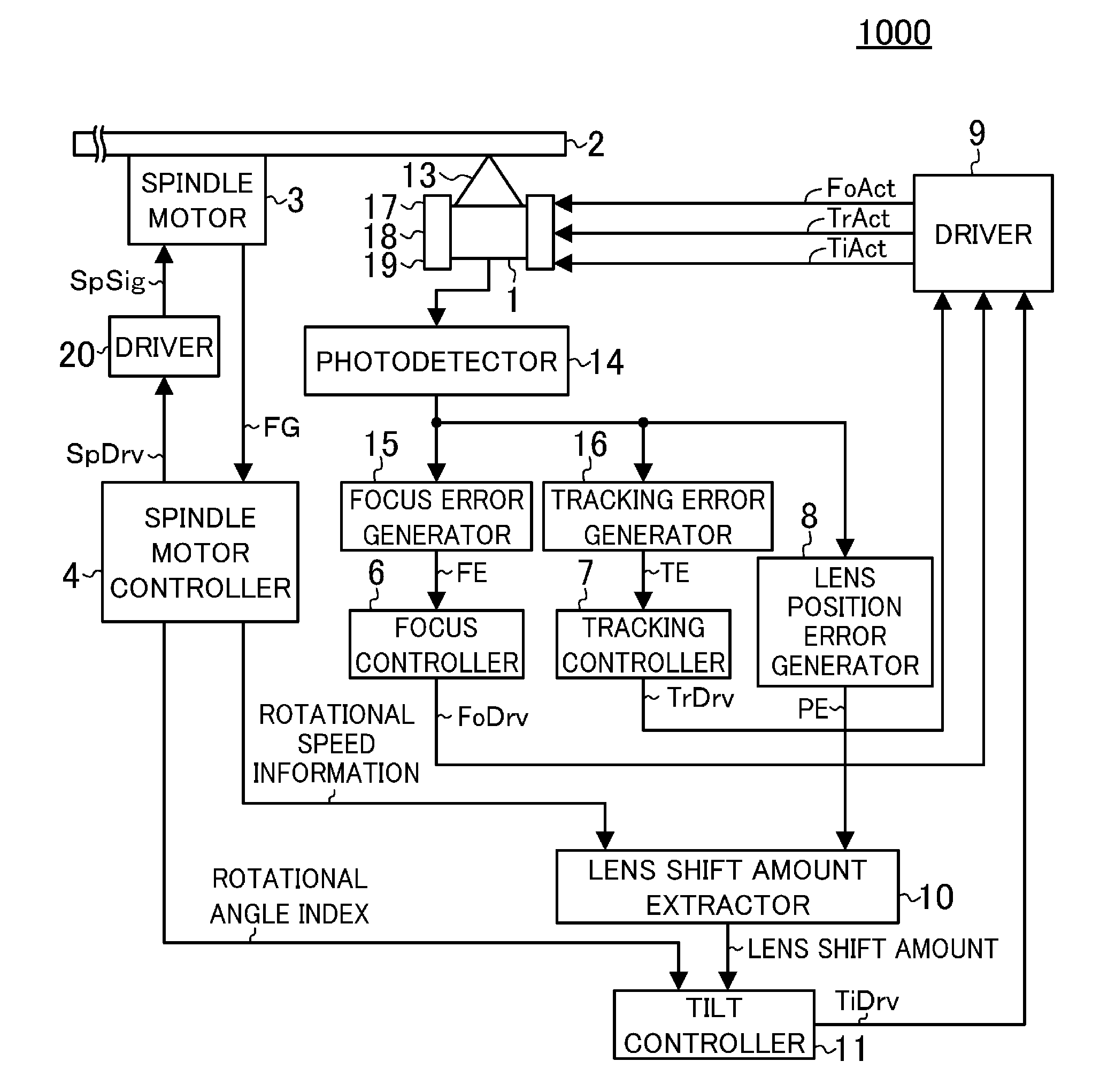
[0024]FIG. 1 is a block diagram showing an optical disk device 1000 according to a first embodiment of the present disclosure. The optical disk device 1000 performs at least one of reproduction and recording of information from and to an optical disk 2 by irradiating the optical disk 2 with laser light 13. Firstly, a focus servo mechanism, a tracking servo mechanism, and a spindle motor servo mechanism will be described with reference to FIG. 1.

[0025]An optical pickup 1 irradiates the optical disk 2 with the laser light 13, receives light reflected from the optical disk 2 using a photodetector 14, and converts the reflected light into an electrical signal. The electrical signal obtained by conversion of the reflected light is supplied to a focus error generator 15 and a tracking error generator 16.

[0026]The focus error generator 15 detects a deviation between the position of a data layer of the optical disk 2 and the position of a focal point of the laser light 13 based on the elect...

second embodiment

[0053]FIG. 6 is a block diagram showing an optical disk device 1001 according to a second embodiment of the present disclosure. Elements of the optical disk device 1001 of FIG. 6 similar to those of the optical disk device 1000 of FIG. 1 are indicated by the same reference characters and will not be described in detail.

[0054]As shown in FIG. 6, the optical pickup 1 irradiates the optical disk 2 with the laser light 13. During at least one of reproduction and recording of information from and to the optical disk 2, the tracking servo mechanism is active. At this time, the tracking control signal TrDry output from the tracking controller 7 contains information about a position of the objective lens 5 in the radial direction of the optical disk 2. Therefore, the lens shift amount extractor 10 can extract a lens shift amount from the tracking control signal TrDrv. If a lens shift amount is extracted from the tracking control signal TrDrv, the lens position error generator 8 of FIG. 1 ca...

third embodiment

[0059]FIG. 8 is a block diagram showing an optical disk device 1002 according to a third embodiment of the present disclosure. Elements of the optical disk device 1002 of FIG. 8 similar to those of the optical disk device 1000 of FIG. 1 are indicated by the same reference characters and will not be described in detail.

[0060]As shown in FIG. 8, either the tracking control signal TrDry or the lens position error signal PE is selected by a signal selector 12, and supplied as a signal Y to the lens shift amount extractor 10. The lens shift amount extractor 10 receives the rotational speed information of the spindle motor 3 generated by the spindle motor controller 4 and the signal Y selected by the signal selector 12, and eliminates rotation components of the optical disk 2, high-frequency components which do not include lens shift components, etc., which are contained in the signal Y, to extract a lens shift amount. An LPF, a BEF, etc. can be used as a filter for eliminating the rotati...


PUM


Abstract

In an optical disk device, a technique for AC tilt correction with stability and following capability is provided in which, during an operation of a tracking servo mechanism, a lens shift amount obtained from a tracking control signal or a lens position error signal is measured for each of predetermined angles of rotation of an optical disk, and the measured values are averaged in a radial direction of the optical disk, and a tilt controller corrects an AC tilt based on the resulting average value.

Description

CROSS-REFERENCE TO RELATED APPLICATION[0001]This is a continuation of PCT International Application PCT / JP2012 / 001695 filed on Mar. 12, 2012, which claims priority to Japanese Patent Application No. 2011-088981 filed on Apr. 13, 2011. The disclosures of these applications including the specifications, the drawings, and the claims are hereby incorporated by reference in their entirety.BACKGROUND[0002]The present disclosure relates to techniques of controlling an optical disk device for recording and reproducing information by irradiating a recording surface of an optical disk with laser light so that a tilt of an objective lens which is caused by a displacement of the objective lens is adjusted.[0003]When recording and reproduction are performed on an optical disk using an optical disk device, the objective lens rolls due to tracking drive, so that the objective lens is tilted in a radial direction of the optical disk with respect to a recording surface of the optical disk. The tilt ...

Claims


Application Information

Patent Timeline
IPC IPC(8): G11B7/1392
CPCG11B7/13927G11B7/0956
Inventor KISHIMOTO, TOMONORI
Owner PANASONIC SEMICON SOLUTIONS CO LTD
Why Eureka
Try Eureka