Heat circulation pump

a circulation pump and heat led technology, applied in the direction of pump, positive displacement liquid engine, liquid fuel engine, etc., can solve the problems of introducing into the terminal box, and a large part of the heat led via the earthing contact does not get into the terminal box at all, so as to reduce manufacturing and assembly costs

Active Publication Date: 2014-01-30
GRUNDFOS MANAGEMENT AS
View PDF3 Cites 12 Cited by
  • Summary
  • Abstract
  • Description
  • Claims
  • Application Information

AI Technical Summary

Benefits of technology

[0004]Such heating circulation pumps of a small or medium construction type are produced in large-scale manufacture, which is why even the smallest improvements can entail significant savings with regard to manufac

Problems solved by technology

The heat which is introduced into the terminal box from the motor housing via the earthing contact however is significantly lower than with known designs, since a branching of the heat flows also occurs due

Method used


Image

  • Heat circulation pump
  • Heat circulation pump
  • Heat circulation pump

Examples


Embodiment Construction

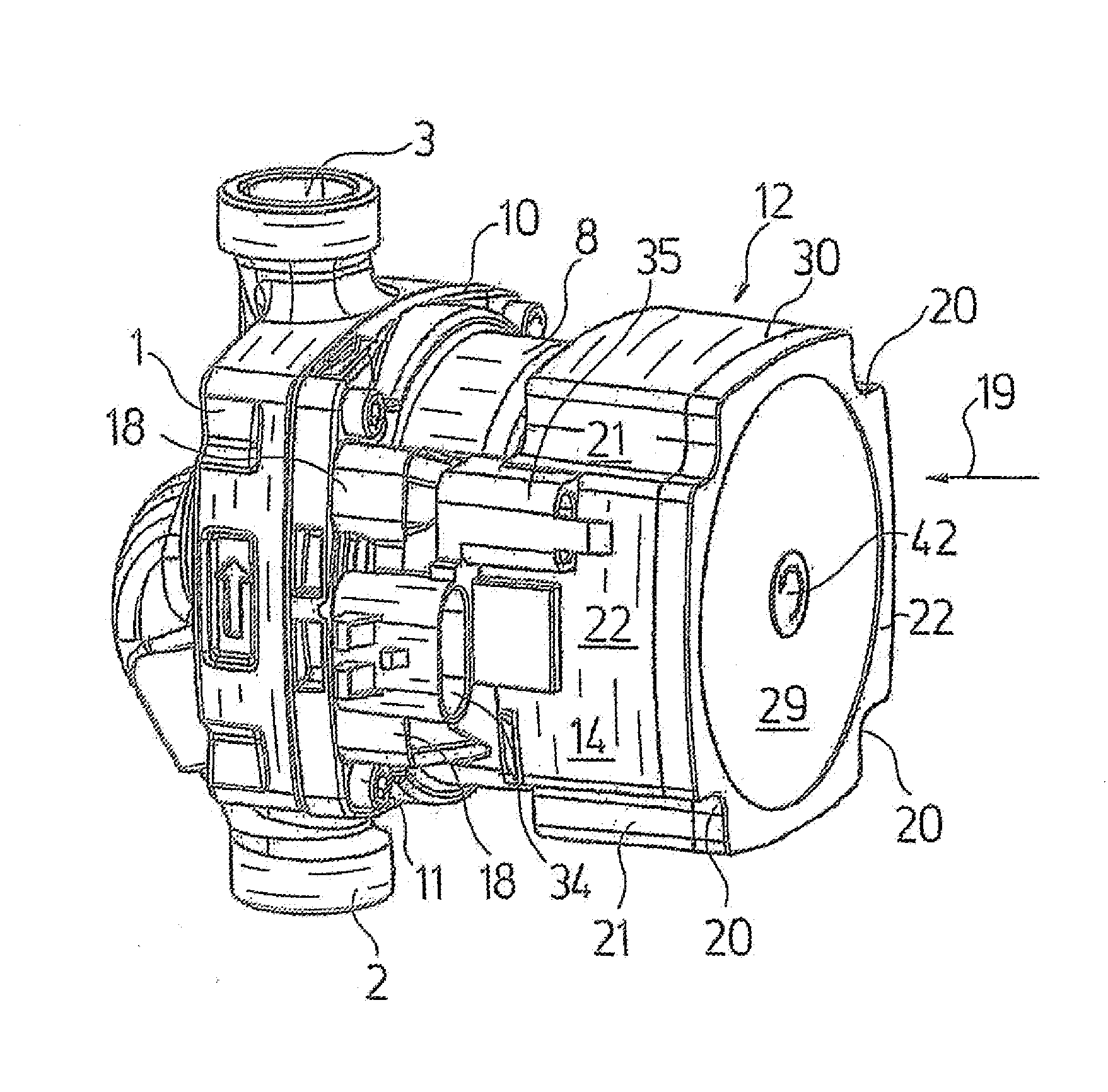
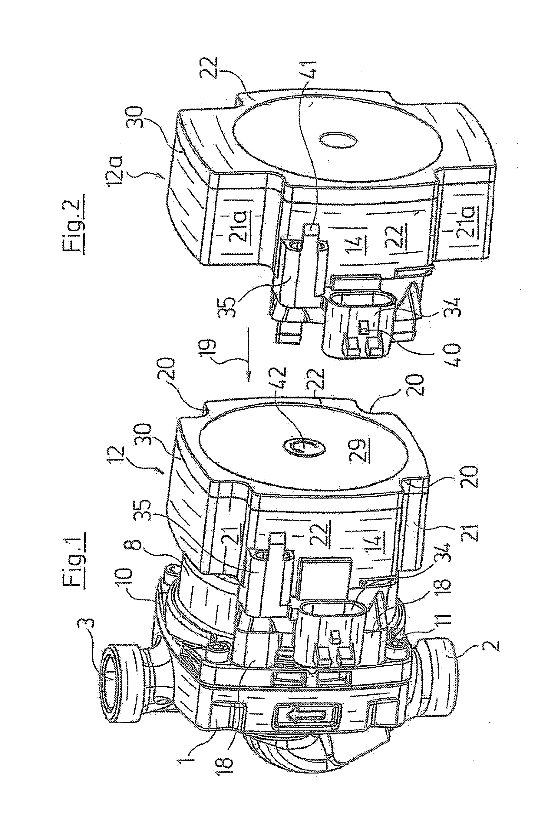
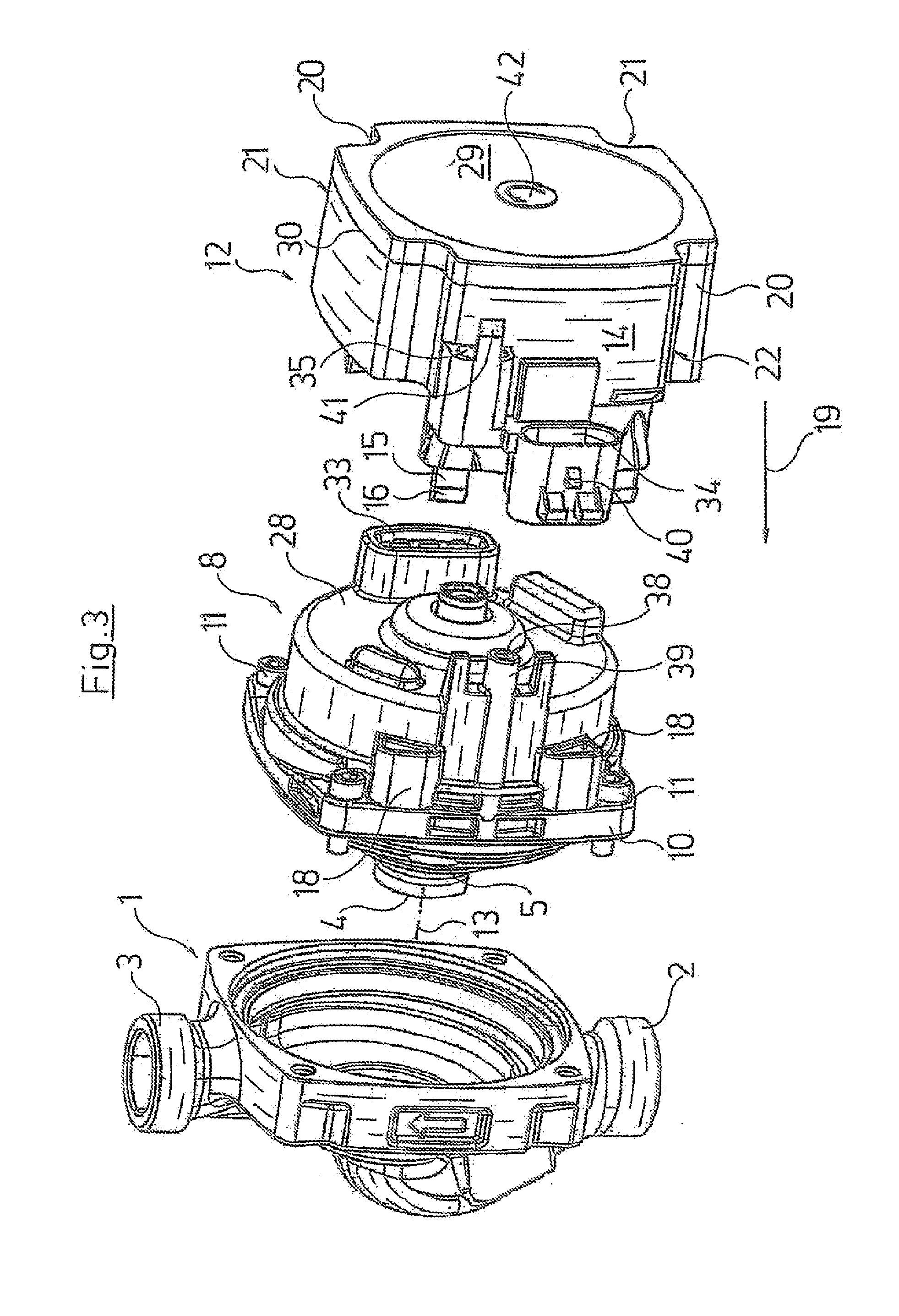
[0030]Referring to the drawings in particular, the heating circulation pump represented by way of FIGS. 1 and 3 and 8 comprises a centrifugal pump with a pump housing 1 with a suction nozzle 2 and with a pressure nozzle 3 with a channel guidance formed therebetween which leads the fluid coming from the suction nozzle 2 to a suction port 4 of a pump impeller 5 which is mounted within the pump housing 1 and whose driven side connects to a channel leading to the pressure nozzle 3.

[0031]The heating circulation pump moreover comprises a motor, here a wet-running motor, whose rotor 6 runs in a can 7 which is filled with fluid. The can 7 is surrounded by a stator, i.e. by the motor windings arranged around the can 7 on the peripheral side, as well as by a motor housing 8 receiving the stator. The rotor 6 comprises a central shaft 9 which extends to into the pump housing 1 and carries the pump impeller 5, so that the rotational movement of the rotor 6 is transmitted onto the pump impeller 5...


PUM


Abstract

A heat circulation pump includes a pump housing (1) with a pump impeller driven by an electric motor. The electric motor is arranged in a motor housing (8) connected to the pump housing (1). A plastic terminal box (12) is fixed to the motor housing (8) and houses electric and/or electronic components of the engine control and electrically connects the motor, a ground contact arranged on the motor housing (8), and a plug and or a socket (34) arranged on the outside of the terminal box (12). The ground contact is connected in an electrically conductive manner to a ground contact of the plug or socket (34) and to at least one conductor inside the terminal box (12). The electric connection between the ground contact arranged on the motor housing (8) and the ground contact of the plug or socket (34) is arranged outside of the terminal box (12).

Description

CROSS REFERENCE TO RELATED APPLICATIONS[0001]This application is a United States National Phase Application of International Application PCT / EP2012 / 053221 filed Feb. 24, 2012 and claims the benefit of priority under 35 U.S.C. § 119 of European Patent Application EP 11002072.4 filed Mar. 12, 2011, the entire contents of which are incorporated herein by reference.FIELD OF THE INVENTION[0002]The invention relates to a heating circulation pump with a pump housing, with a pump impeller arranged therein and which is driven by an electric motor arranged in a motor housing connected to the pump housing. A terminal box of plastic is fastened on the motor housing and is for receiving electrical and / or electronic components of the motor control as well as for the electrical connection of the motor, with an earthing (ground) contact arranged on the motor housing and with a plug or socket of an electric plug-in connection for the electric connection. The plug or socket is arranged at the outside...

Claims


Application Information

Patent Timeline
IPC IPC(8): F04D25/06
CPCF04D25/06F04D13/0606F04D13/0626F04D13/0686F04D13/0693F04D29/026F04D29/426F04D29/5893H02K5/10H02K5/225H02K7/14H02K11/33H02K5/128F04D13/06
Inventor HOJ, FINN MATHIESENBLAD, THOMAS
Owner GRUNDFOS MANAGEMENT AS
Why Eureka
Try Eureka