Vacuum thermal bonding apparatus and vacuum thermal bonding method

a vacuum thermal bonding and vacuum thermal bonding technology, applied in the direction of manufacturing tools, sustainable manufacturing/processing, final product manufacturing, etc., can solve the problems of difficult sealing, broken sealing corners, and difficulty in well bonding or sealing elements on the substra

Active Publication Date: 2014-02-06
MIKADO TECHNOS
View PDF11 Cites 15 Cited by
  • Summary
  • Abstract
  • Description
  • Claims
  • Application Information

AI Technical Summary

Benefits of technology

[0009]The following effects are obtained according to the vacuum

Problems solved by technology

However, contrary to the expectation, it was difficult to well bond or seal the element onto the substrate, while the runout of the adhesive was minimized.
In addition, when the element is sealingly bonded to the substrat

Method used


Image

  • Vacuum thermal bonding apparatus and vacuum thermal bonding method
  • Vacuum thermal bonding apparatus and vacuum thermal bonding method
  • Vacuum thermal bonding apparatus and vacuum thermal bonding method

Examples


first embodiment

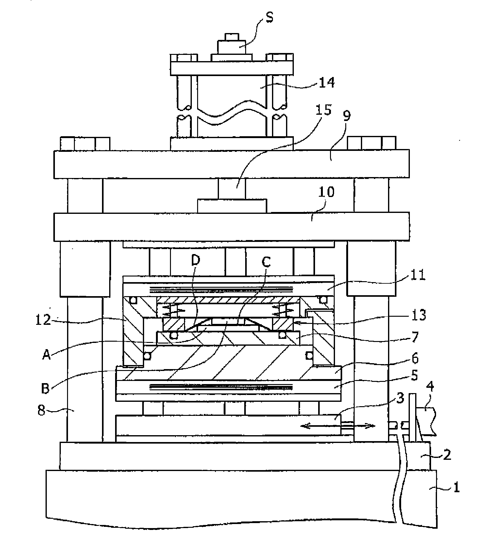
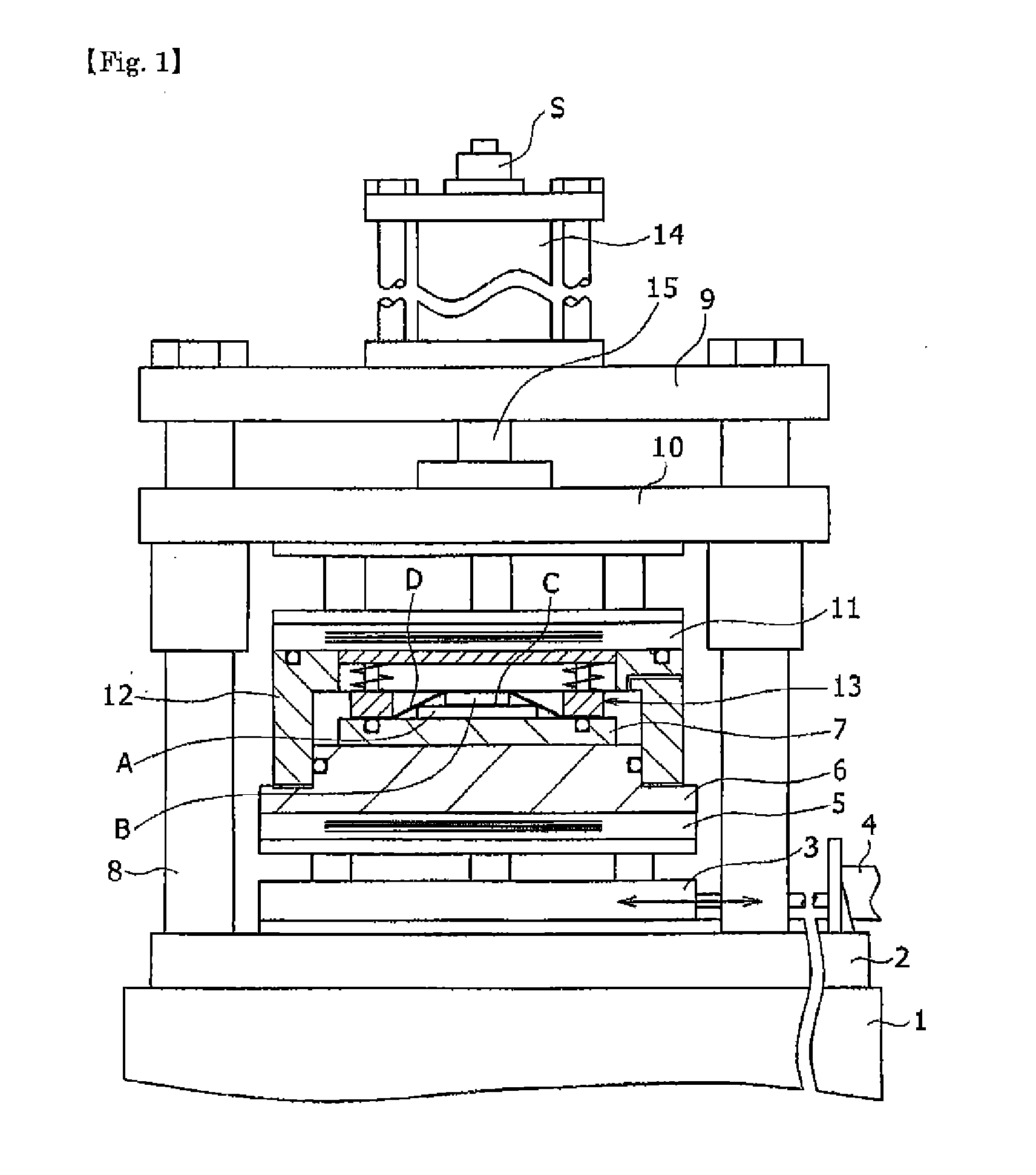
[0030]FIG. 1 shows a vacuum thermally bonding apparatus according to a first embodiment of the present invention. In this vacuum thermally bonding apparatus, a press cylinder lower plate 2 is arranged on a base 1, a slidably moving table 3 is arranged on the press cylinder lower plate 2 such that the moving table can be moved between the inside and the outside of the vacuum thermally bonding apparatus by a slide cylinder 4. A lower heater plate 5 is arranged adiabatically above the slidably moving table 3, a lower plate member 6 is placed on an upper face of the lower heater plate 5, and a substrate-placing table 7 is placed on an upper face of the lower plate member.

[0031]A plurality of support poles 8 are arranged on and erected from the press cylinder lower plate 2, and a press cylinder upper plate 9 is fixed at upper ends of the support poles 8. The support poles 8 may be erected directly on the base 1. An intermediate moving member (intermediate member) 10 is arranged under the...


PUM

PropertyMeasurementUnit
Pressureaaaaaaaaaa

Abstract

A vacuum thermally bonding apparatus is provided, in which while air is being prevented in vacuum from entering a bonding layer, an element is thermally bonded to a substrate under vacuum by forming the bonding layer. A lower end portion of an upper frame member is gas-tightly slidably sealed to a peripheral portion of the lower plate member to form a vacuum partition wall therein, and a pressurizing release film is contacted with an upper face of the element, and thermally softened in the atmospheric pressure. A vacuum chamber is evacuated to vacuum, and the lower plate member and an intermediate member are relatively moved in an approaching direction, so that an outer peripheral portion of the pressurizing release film is gas-tightly held between the upper face of the substrate-placing table of the lower plate member and a lower face of an inner frame body.

Description

TECHNICAL FIELD[0001]The present invention relates to a vacuum thermal bonding apparatus and a vacuum thermal bonding method for bonding an element such as a semiconductor, a resistance and / or a condenser to a substrate, bonding this substrate to a heat-dissipating plate, and imprint transferring or bonding a film sheet such as an ITO film.BACKGROUND ART[0002]When an element such as a semiconductor, a resistance and / or a condenser to a substrate is to be bonded or sealed to a substrate, they are bonded together with use of an insulating adhesive or an electroconductive adhesive between the substrate and the element. When the adhesive layer is press worked, the adhesive runs over so that a bonding capacity of the insulating layer or the electroconductive layer formed decreases to deteriorate the performance.[0003]The present applicant proposed an apparatus for hot pressing a thin plate-like workpiece to be used in covering, with a protective sheet made of a thermosetting adhesive, a ...

Claims


Application Information

Patent Timeline
IPC IPC(8): H05K3/30
CPCH05K3/305H01L24/32H01L24/75H01L24/83H01L2224/32225H01L2224/75102H01L2224/75315H01L2224/75316H01L2224/83001H01L2224/83203B30B5/02B30B11/027B30B15/34B32B37/1009B32B37/1284B32B2457/12B32B2457/14H01L2224/2929H01L2224/293H01L2224/75101H01L2224/75317H01L2224/8309H01L2224/83191H01L2224/83209H01L2924/07802Y10T29/53174Y10T29/53191Y02P70/50H01L2924/00014H01L2924/00
Inventor ITO, TAKASHISATO, HIROKI
Owner MIKADO TECHNOS
Why Eureka
Try Eureka