Controller for Gas Turbine Power Plant

Active Publication Date: 2014-02-06
MITSUBISHI POWER LTD
View PDF9 Cites 9 Cited by
  • Summary
  • Abstract
  • Description
  • Claims
  • Application Information

AI Technical Summary

Benefits of technology

[0020]The aspect of the present invention controls the water atomization flow rate or/and the air flow rate so as to compensate in advance for fluctuations in the fuel-air ratio occurring as a result of the combustion switching. Unsteady combustion at the time of combustion switching can thus be

Problems solved by technology

Spraying water drops over the combustion air improves the output thanks to a reduced air temperature and an increased air flow rate on one hand; but, on

Method used


Image

  • Controller for Gas Turbine Power Plant
  • Controller for Gas Turbine Power Plant
  • Controller for Gas Turbine Power Plant

Examples


first embodiment

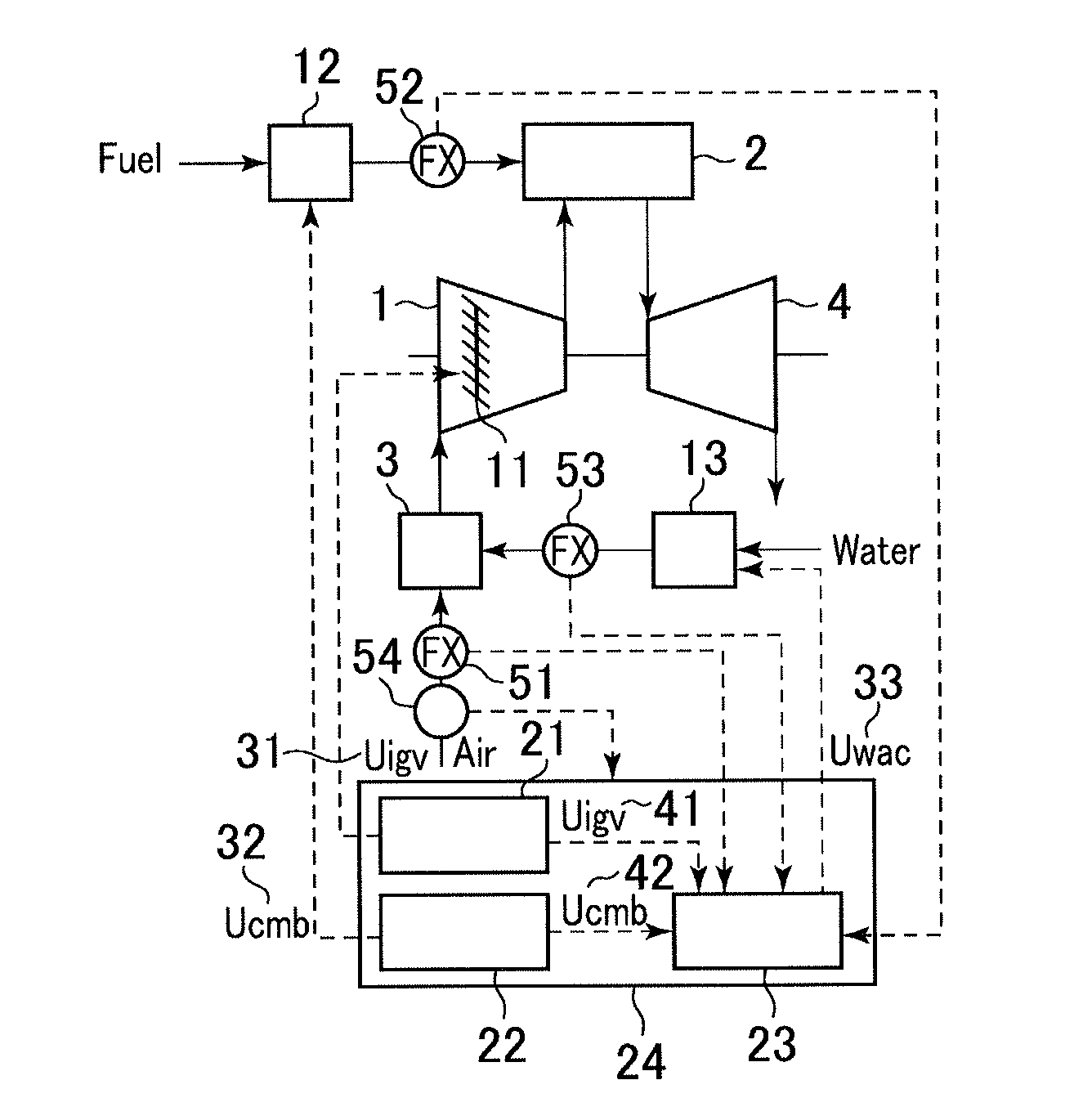
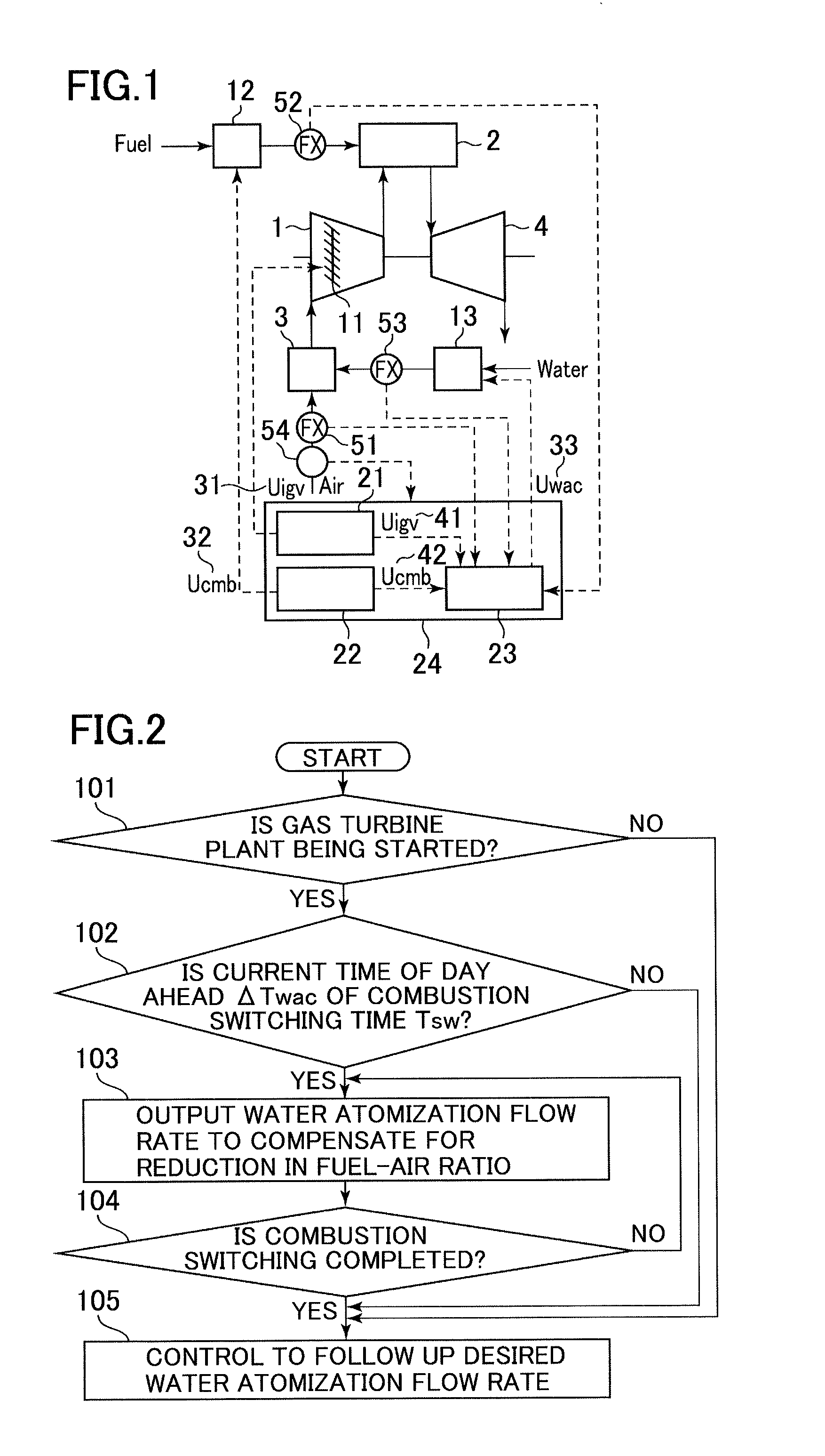
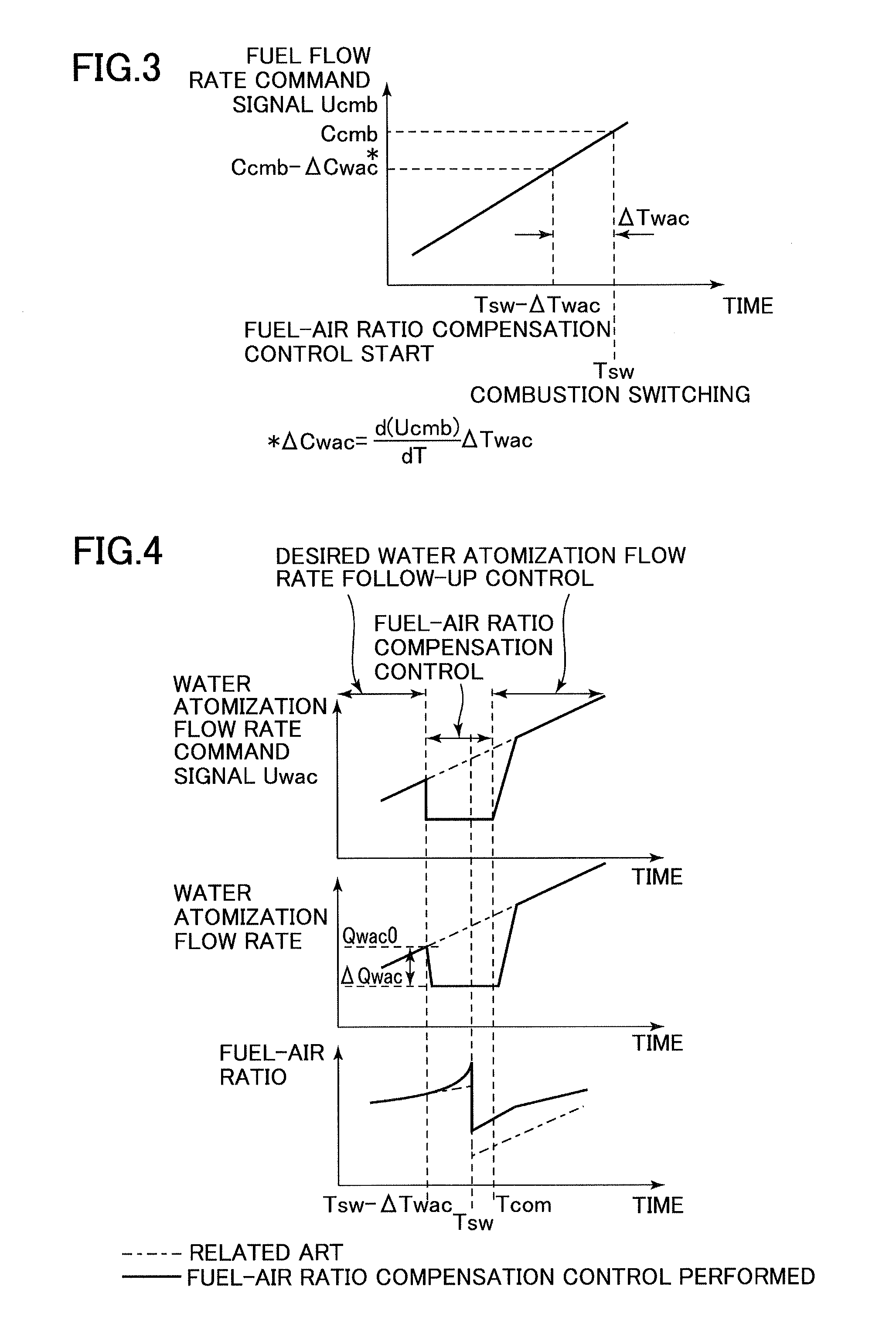
[0033]A controller for a gas turbine power plant according to a first embodiment of the present invention will be described below with reference to the accompanying drawings. FIG. 1 is a system configuration diagram showing a gas turbine power plant including the controller for a gas turbine power plant according to the first embodiment of the present invention. FIG. 2 is a flowchart showing processing steps performed by the controller for a gas turbine power plant according to the first embodiment of the present invention. FIG. 3 is a characteristic diagram showing a characteristic of a water atomization flow rate command signal in the controller for a gas turbine power plant according to the first embodiment of the present invention. FIG. 4 is a characteristic diagram depicting a fuel flow rate command signal characteristic (upper diagram), a water atomization flow rate characteristic (middle diagram), and a fuel-air ratio characteristic (lower diagram) in the controller for a gas...

second embodiment

[0066]A controller for a gas turbine power plant according to a second embodiment of the present invention will be described below with reference to the accompanying drawings. FIG. 5 is a system configuration diagram showing a gas turbine power plant including the controller for a gas turbine power plant according to the second embodiment of the present invention. FIG. 6 is a flowchart showing processing steps performed by the controller for a gas turbine power plant according to the second embodiment of the present invention. FIG. 7 is a characteristic diagram depicting an air flow rate command signal characteristic (upper diagram), an air flow rate characteristic (middle diagram), and a fuel-air ratio characteristic (lower diagram) in the controller for a gas turbine power plant according to the second embodiment of the present invention. In FIGS. 5 to 7, like or corresponding parts are identified by the same reference numerals as those used in FIGS. 1 to 4 and detailed descriptio...

third embodiment

[0084]A controller for a gas turbine power plant according to a third embodiment of the present invention will be described below with reference to the accompanying drawings. FIG. 8 is a characteristic diagram depicting an air flow rate command signal characteristic (upper diagram) and a fuel-air ratio characteristic (lower diagram) in the controller for a gas turbine power plant according to the third embodiment of the present invention. In FIG. 8, like or corresponding parts are identified by the same reference numerals as those used in FIGS. 1 to 7 and detailed descriptions for those parts will be omitted.

[0085]The gas turbine power plant according to the third embodiment of the present invention represents a combination of the first and second embodiments of the present invention. The gas turbine power plant according to the third embodiment of the present invention includes a controller 24 that causes a water atomization cooling apparatus 3 to start spraying water drops prior t...


PUM


Abstract

A controller for use in a gas turbine power plant includes a compressor that compresses combustion air; a water-atomization cooling apparatus that sprays water drops of atomized water supplied via a water-atomization flow-rate regulating valve over a flow of air drawn in the compressor; a combustor that mixes the compressed combustion air with fuel to thereby burn a fuel-air mixture and generate combustion gas at high temperature and performs combustion switching during operation; a turbine that uses the combustion gas to drive the compressor and a generator; the water-atomization flow-rate regulating valve that controls a flow rate of the atomized water; and a compressor inlet inner blade that controls a flow rate of air drawn in the compressor. The controller includes control means that calculates a fuel-air ratio correction command signal for compensating for reduction in a fuel-air ratio in the combustor occurring during the combustion switching.

Description

TECHNICAL FIELD[0001]The present invention relates to a controller for a gas turbine power plant including a compressor, a combustor, a turbine, and a generator.BACKGROUND ART[0002]A gas turbine power plant generally includes a compressor that compresses combustion air, a combustor that mixes the compressed combustion air with gas turbine fuel (hereinafter referred to as fuel) to thereby burn a fuel-air mixture and generate combustion gas at high temperature, and a turbine that uses the combustion gas to drive the compressor and a generator.[0003]A pre-mixed combustion system that mixes air with fuel in advance of combustion is employed as a fuel control system for such a gas turbine power plant in order to reduce nitrogen oxide emissions produced in the combustor. In the pre-mixed combustion system, the combustor is configured to include a plurality of burners and fuel systems. By using these burners and fuel systems, a pre-mixed combustion portion of the combustor is divided into ...

Claims


Application Information

Patent Timeline
IPC IPC(8): F02C9/00
CPCF02C9/00F02C3/30F02C9/20F02C7/1435
Inventor KIM, EUNKYEONGKOYAMA, KAZUHITOHATAMIYA, SHIGEOKATAGIRI, YUKINORIYOSHIDA, TAKUYAKUSUMI, NAOHIROTAKAHASHI, KAZUO
Owner MITSUBISHI POWER LTD
Why Eureka
Try Eureka