
Electric Generator

Inactive Publication Date: 2014-02-06
KSB AG
View PDF0 Cites 5 Cited by
  • Summary
  • Abstract
  • Description
  • Claims
  • Application Information

AI Technical Summary

Benefits of technology

The main object of this patent is to provide a highly efficient and cost-effective generator. The generator has a rotating electric machine with low electrical losses and high performance. It also has lower maintenance requirements and is more durable than conventional generators. This allows for better performance with smaller control means.

Problems solved by technology

While this kind of electric machine has a sturdy structure and is particularly advantageous in terms of costs, it still suffers from certain drawbacks.
A first drawback is that asynchronous machines have substantially large dimensions and heavy weights, especially when associated with medium-to-high electric generators, e.g. 500 kW generators.
A further drawback is that these machines have non negligible electrical losses, which considerably reduce the efficiency of the generator.
Nevertheless, permanent magnet machines have a higher cost than double-fed asynchronous machines.
A particular drawback of this solution is that, in particular operating conditions, the defluxing current may have a high value and require oversized control means.
Furthermore, in particular transients, defluxing may cause higher electrical losses from the windings of the electric machine, due to the Joule effect.
Nevertheless, these prior art machines have very low electrical efficiencies and are also characterized by high torque ripple.

Method used


Image

  • Electric Generator
  • Electric Generator
  • Electric Generator

Examples


Embodiment Construction

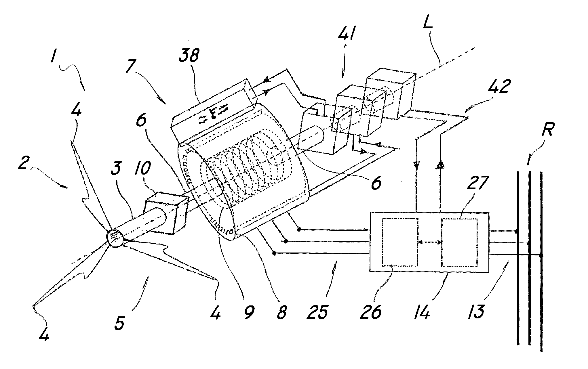
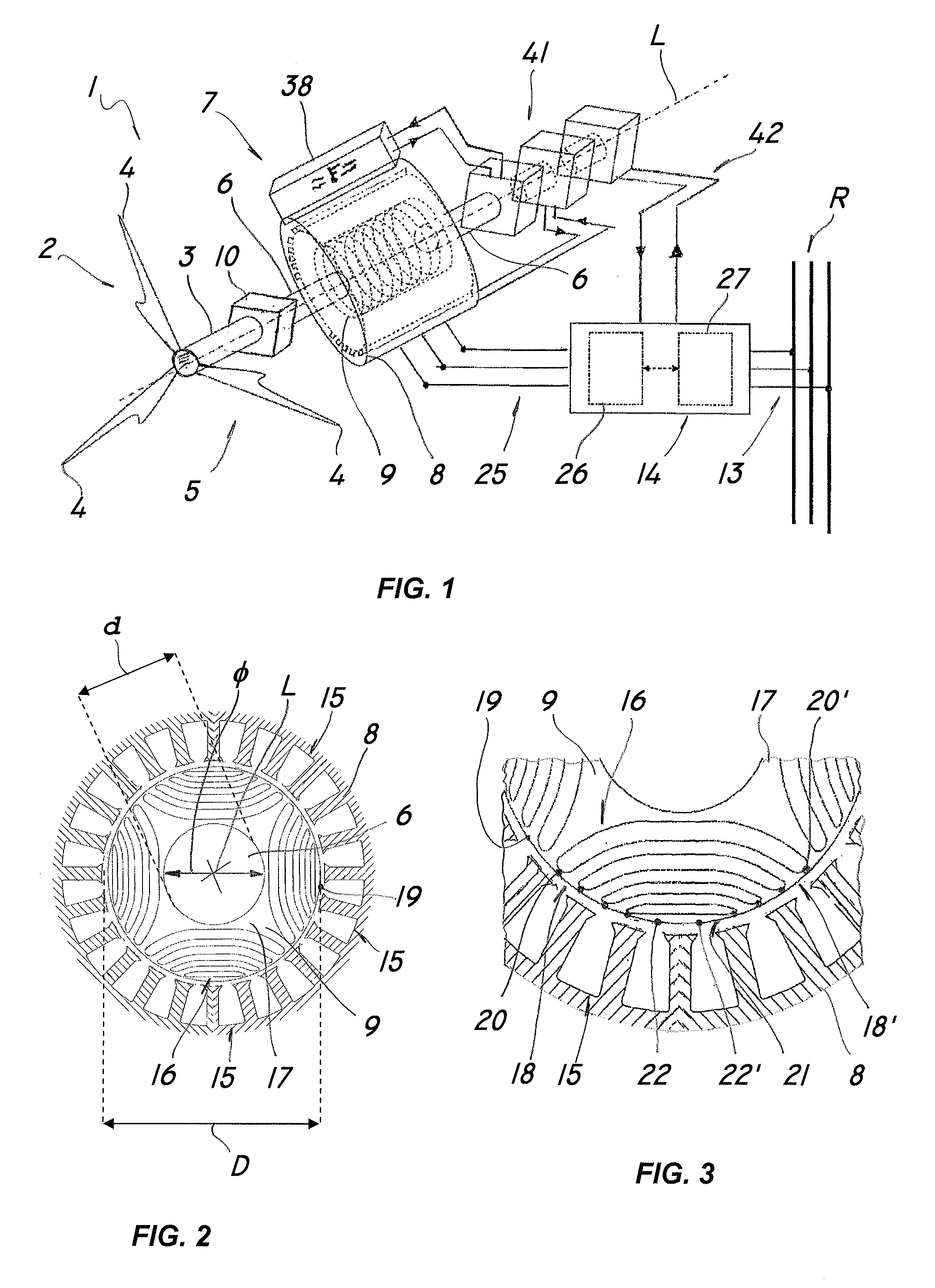
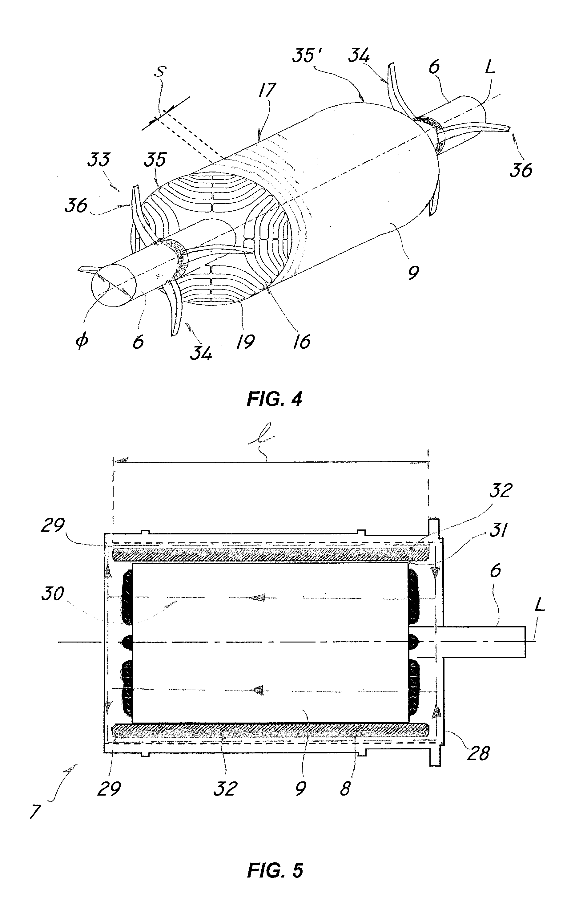
[0041]Referring to the above figures, the generator of the invention, generally referenced 1, may be used in systems for producing electric energy from fossil or chemical energy sources, or renewable energy, such as wind or water energy.

[0042]The figures show, as a non limiting example, a generator 1 that utilizes a renewable energy source, particularly an aeroturbine 2. It will be appreciated that the aeroturbine 2 may be replaced by a water or steam turbine, i.e. a fossil fueled internal combustion engine.

[0043]The wind generator 1 may be used both for small-to-medium power systems, such as in civil and industrial installations, and for high-power systems in terrestrial or on-shore or off-shore installations.

[0044]Furthermore, the generator 1 may have a horizontal-axis or vertical-axis design and be wholly contained in a nacelle, not shown, located at the end of the tower, also not shown.

[0045]The generator 1 comprises a driving shaft 3 rotating about a longitudinal axis L and ada...


PUM


Abstract

An electric energy generator includes a driving shaft designed to be coupled to an external energy source having a predetermined torque, a synchronous reluctance rotating electric machine having a stator and a transverse-laminated rotor, and a driven shaft operatively coupled to the drive shaft for generating electric energy with a predetermined torque ripple amplitude, an electric connection for injecting the electric energy so generated into the net, a control system designed to adjusting electrical and dynamic parameters of the electric machine. The stator has an even number of longitudinal grooves for each pair of poles and the rotor has a plurality of adjacent slots defining an even number of magnetically equivalent slots. The number of grooves is different from the number of equivalent slots multiplied by an integer, the difference between the number of grooves and the number of equivalent slots being different form zero, +2 and −2.

Description

FIELD OF THE INVENTION[0001]The present invention generally finds application in the field of electric machines, and particularly relates to an electric energy generator powered by an external motive energy source, particularly of renewable type, such as a wind energy source.BACKGROUND ART[0002]Generators are known to comprise a rotating electric machine having a stator and a rotor coupled to a driving shaft, which is driven by an external energy source, for instance an alternative-energy source, such as a wind energy source, or hydraulic or chemical energy sources.[0003]Furthermore, the generator comprises control means for adjusting electrical and dynamic parameters of the electric machine and electric connection means for injecting the electric energy into a supply network or into power storage means, such as electric accumulator units.[0004]A particular type of electric generator comprises double-fed asynchronous electric machine, in which the stator is connected to the external...

Claims


Application Information

Patent Timeline
IPC IPC(8): H02K19/24H02K1/27
CPCH02K1/27H02K19/24H02K7/1823H02K9/18H02K2213/03H02K9/08
Inventor BERTOTTO, EZIO
Owner KSB AG
Learn More