Circuit with adjustable phase delay and a feedback voltage and method for adjusting phase delay and a feedback voltage

a technology of which is applied in the field of circuits with adjustable a method for adjusting phase delay and feedback voltage, can solve the problems of system cost increase, system cost increase, and complicated circuit layout of system, so as to achieve the effect of reducing cos

Active Publication Date: 2014-02-13
LEADTREND TECH
View PDF6 Cites 10 Cited by
  • Summary
  • Abstract
  • Description
  • Claims
  • Application Information

AI Technical Summary

Benefits of technology

[0008]The present invention provides a circuit with adjustable phase delay and a feedback voltage and a method for adjustable phase delay and a feedback voltage. The circuit and the method utilize a delay setting unit to generate a delay time according to an external resistor. Then, a phase delay signal generator can generate phase delay signals corresponding to a plurality of lighting modules according to the delay time and a lighting module dimming signal. In addition, a sample voltage generated by a sample and hold unit can overcome variation of a feedback voltage caused by a minimum voltage selection unit due to different number of turning-on lighting modules of the plurality of lighting modules and different number of the plurality of lighting modules to make a lighting module driving circuit be capable of providing a proper output voltage to the plurality of lighting modules. Therefore, the present has advantages as follows: first, because the present invention can make the lighting module driving circuit be capable of providing the proper output voltage to the plurality of lighting modules, the plurality of lighting modules do not exhibit flickers and luminance variation when the plurality of lighting modules are dimmed; second, because the delay setting unit generates the delay time according to the external resistor, a user can adjust the delay time according to a practical requirement (e.g. reaction time of a thin film transistor liquid crystal display panel); and third, because the phase delay signal generator can generate the phase delay signals corresponding to the plurality of lighting modules according to the delay time and the lighting module dimming signal, the present invention does not need a system to provide a plurality of lighting module dimming signals, and not also need a microprocessor, resulting in the present invention having lower cost. Therefore, the present invention can be applied to backlight modules, lighting modules of lighting equipments, and other light sources needing phase delay.

Problems solved by technology

In the prior art, because a system needs to provide a plurality of pulse width modulation signals to the scanning backlight to achieve the phase delay, the system has a more complicated circuit layout and higher cost.
In another prior art, because a system utilizes a microprocessor to control the phase delay in a digital method, the system has additional cost of the microprocessor.
Thus, the above mentioned prior arts not only increase cost of the system, but also increase complexity of the circuit layout of the system, so the above mentioned prior arts are not the best choices for a user.

Method used


Image

  • Circuit with adjustable phase delay and a feedback voltage and method for adjusting phase delay and a feedback voltage
  • Circuit with adjustable phase delay and a feedback voltage and method for adjusting phase delay and a feedback voltage
  • Circuit with adjustable phase delay and a feedback voltage and method for adjusting phase delay and a feedback voltage

Examples


Embodiment Construction

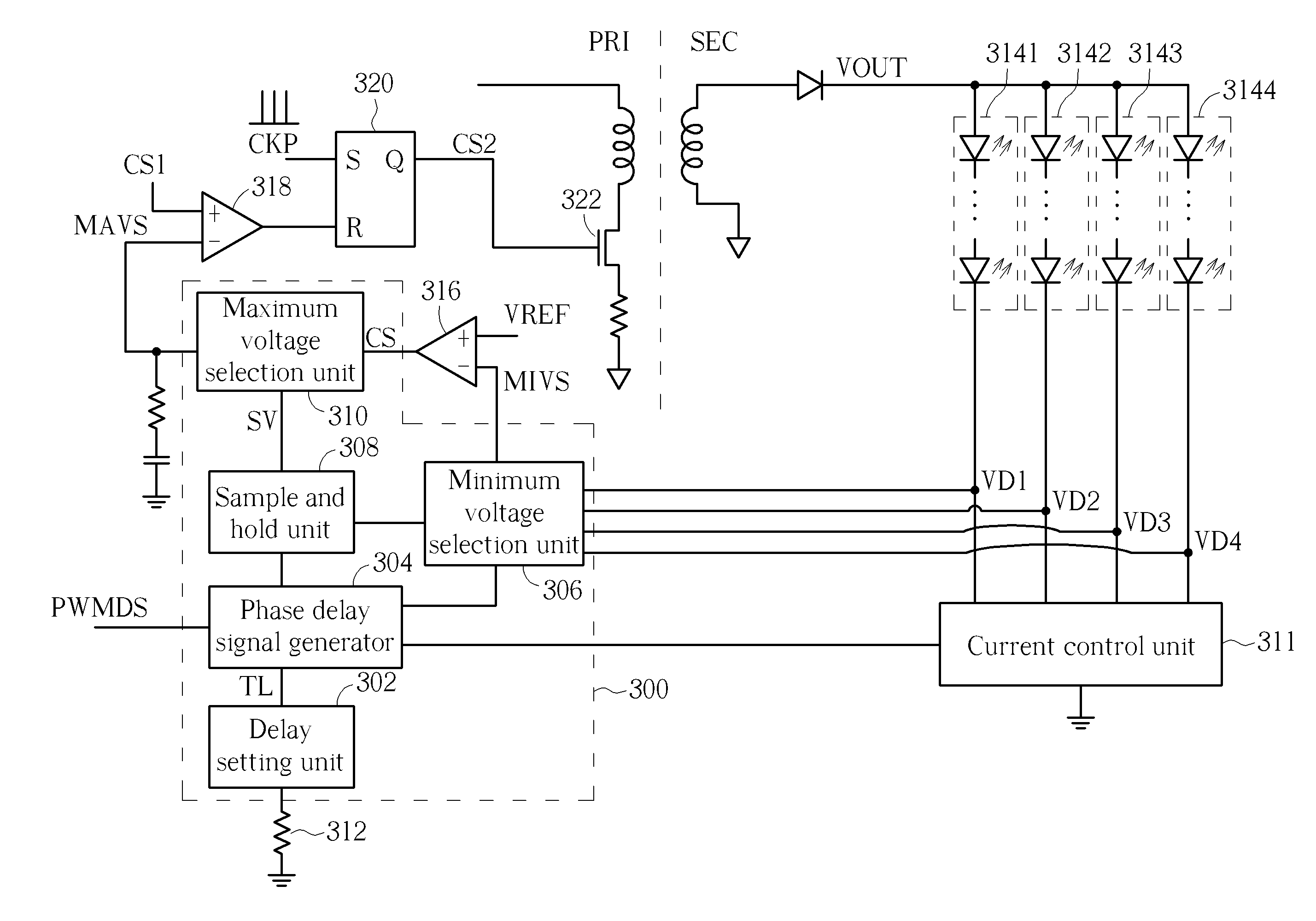
[0016]Please refer to FIG. 3. FIG. 3 is a diagram illustrating a circuit 300 with adjustable phase delay and a feedback voltage according to an embodiment. The circuit 300 includes a delay setting unit 302, a phase delay signal generator 304, a minimum voltage selection unit 306, a sample and hold unit 308, and a maximum voltage selection unit 310, where the maximum voltage selection unit 310, the sample and hold unit 308, the minimum voltage selection unit 306, the delay setting unit 302, and the phase delay signal generator 304 are formed on a monolithic integrated circuit chip. But, the present invention is not limited to the maximum voltage selection unit 310, the sample and hold unit 308, the minimum voltage selection unit 306, the delay setting unit 302, and the phase delay signal generator 304 being formed on the monolithic integrated circuit chip. That is to say, the maximum voltage selection unit 310, the sample and hold unit 308, the minimum voltage selection unit 306, the...


PUM


Abstract

A circuit with adjustable phase delay and a feedback voltage includes a delay setting unit and a phase delay signal generator. The delay setting unit generates a delay time according to an external resistor. The phase delay signal generator includes a plurality of phase delay units. Each phase delay unit includes an edge trigger subunit and a signal generation subunit. The edge trigger subunit receives an input signal, and generates a positive edge trigger signal and a negative edge trigger signal according to a positive edge and a negative edge of the input signal, respectively. The signal generation subunit generates and outputs a phase delay signal according to the positive edge trigger signal, the negative edge trigger signal, and the delay time. The phase delay signal lags the input signal for the delay time.

Description

BACKGROUND OF THE INVENTION[0001]1. Field of the Invention[0002]The present invention relates to a circuit with adjustable phase delay and a feedback voltage and a method for adjustable phase delay and a feedback voltage, and particularly to a circuit and a method that can utilize a delay setting unit, a phase delay signal generator, and a sample and hold unit to generate adjustable phase delay and a stable feedback voltage.[0003]2. Description of the Prior Art[0004]Please refer to FIG. 1 and FIG. 2. FIG. 1 is a diagram illustrating a thin film transistor liquid crystal display (TFT-LCD) generating ghost shadows due to long liquid crystal reaction time, and FIG. 2 is a diagram illustrating the thin film transistor liquid crystal display utilizing a scanning backlight to solve the ghost shadows due to the long liquid crystal reaction time. As shown in FIG. 1, a viewer can view ghost shadows at an interval T because the liquid crystal reaction time is longer and a backlight BL is cont...

Claims


Application Information

Patent Timeline
Patent Type & Authority Applications(United States)
IPC IPC(8): H05B37/02H05B44/00
CPCH05B37/02H05B45/00H05B47/10H05B45/325H05B45/10
Inventor LEE, HUNG-CHINGYAU, YEU-TORNGHUANG, WEI-CHI
Owner LEADTREND TECH
Why Eureka
Try Eureka