Charging device and charging method

a charging device and battery technology, applied in battery/fuel cell control arrangement, battery/fuel cell control, electrochemical generators, etc., can solve the problem of charging time becoming an issue, and achieve the effect of reducing the temperature increase of the vehicle-mounted power storage device and long-distance running

Inactive Publication Date: 2014-02-13
TOYOTA JIDOSHA KK
View PDF2 Cites 114 Cited by
  • Summary
  • Abstract
  • Description
  • Claims
  • Application Information

AI Technical Summary

Benefits of technology

[0020]According to the present invention, charging and discharging can be carried out while suppressing temperature increase of a vehicle-mounted power storage device, as well as allowing long-distance running.

Problems solved by technology

When a vehicle-mounted battery is to be charged from an external source, the time required for charging becomes an issue.

Method used


Image

  • Charging device and charging method
  • Charging device and charging method
  • Charging device and charging method

Examples


first embodiment

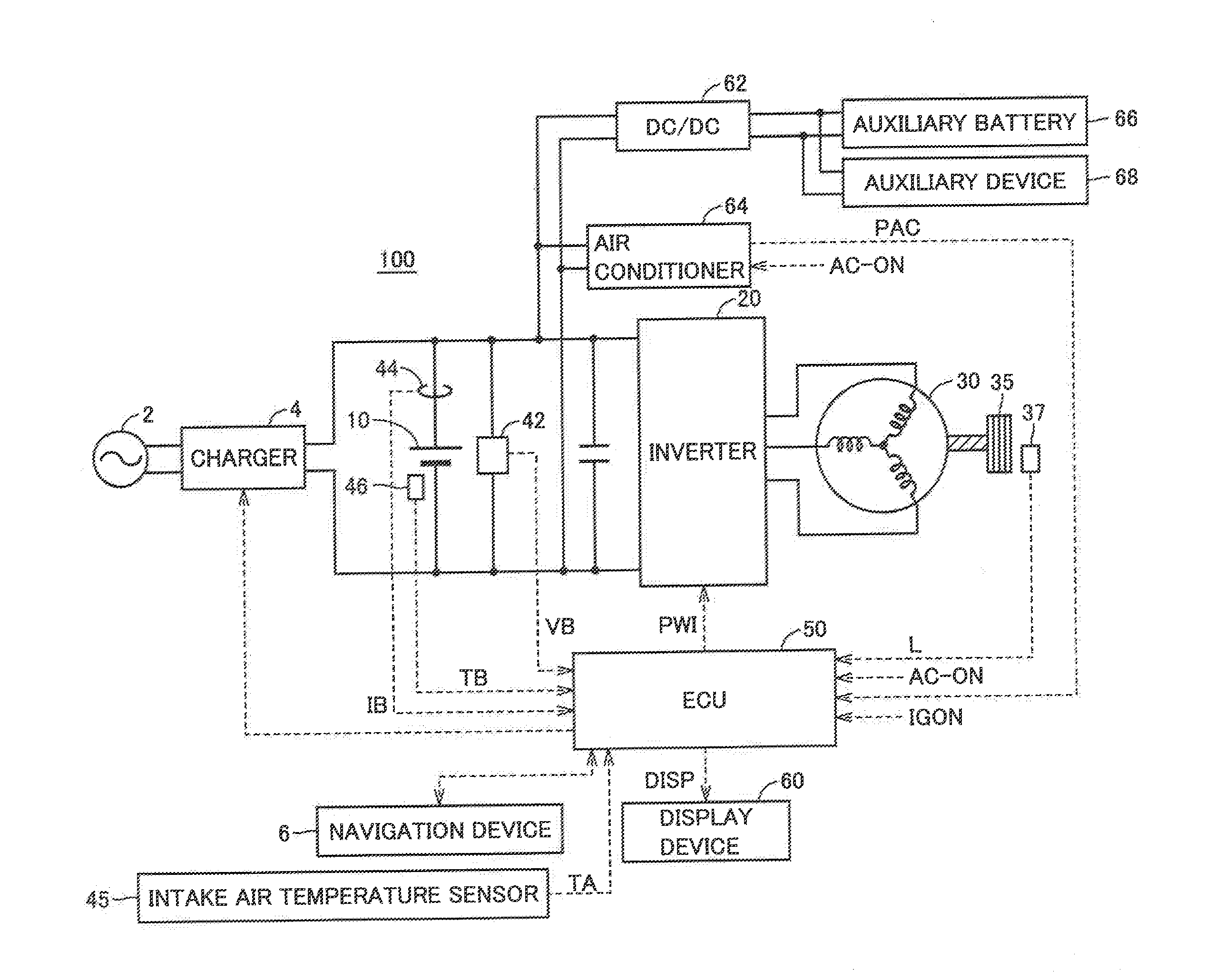
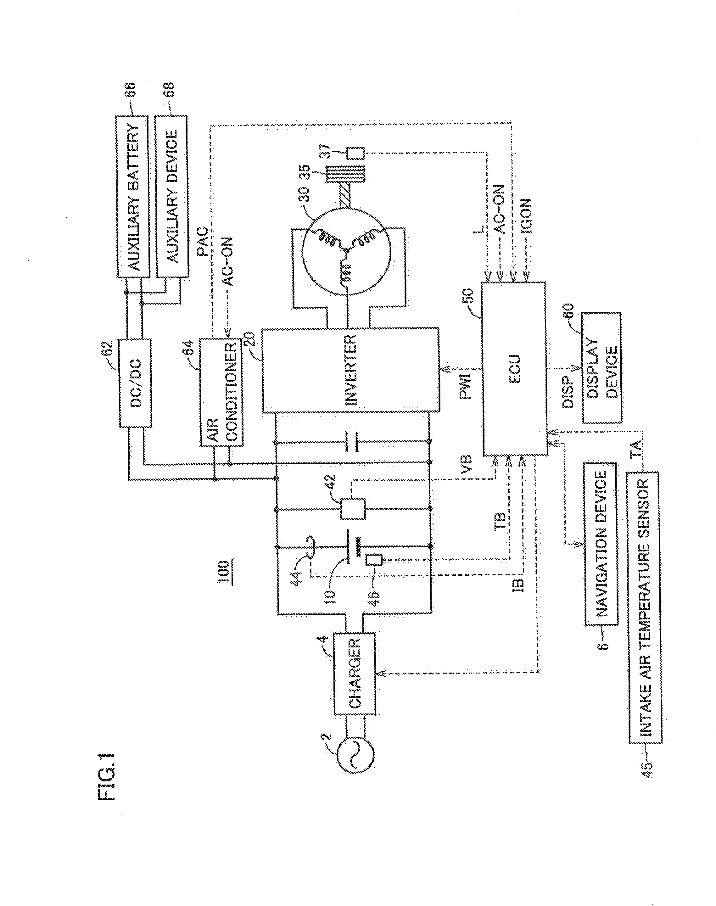
[0030]FIG. 1 is an entire block diagram of an electric powered vehicle according to an embodiment of the present invention.

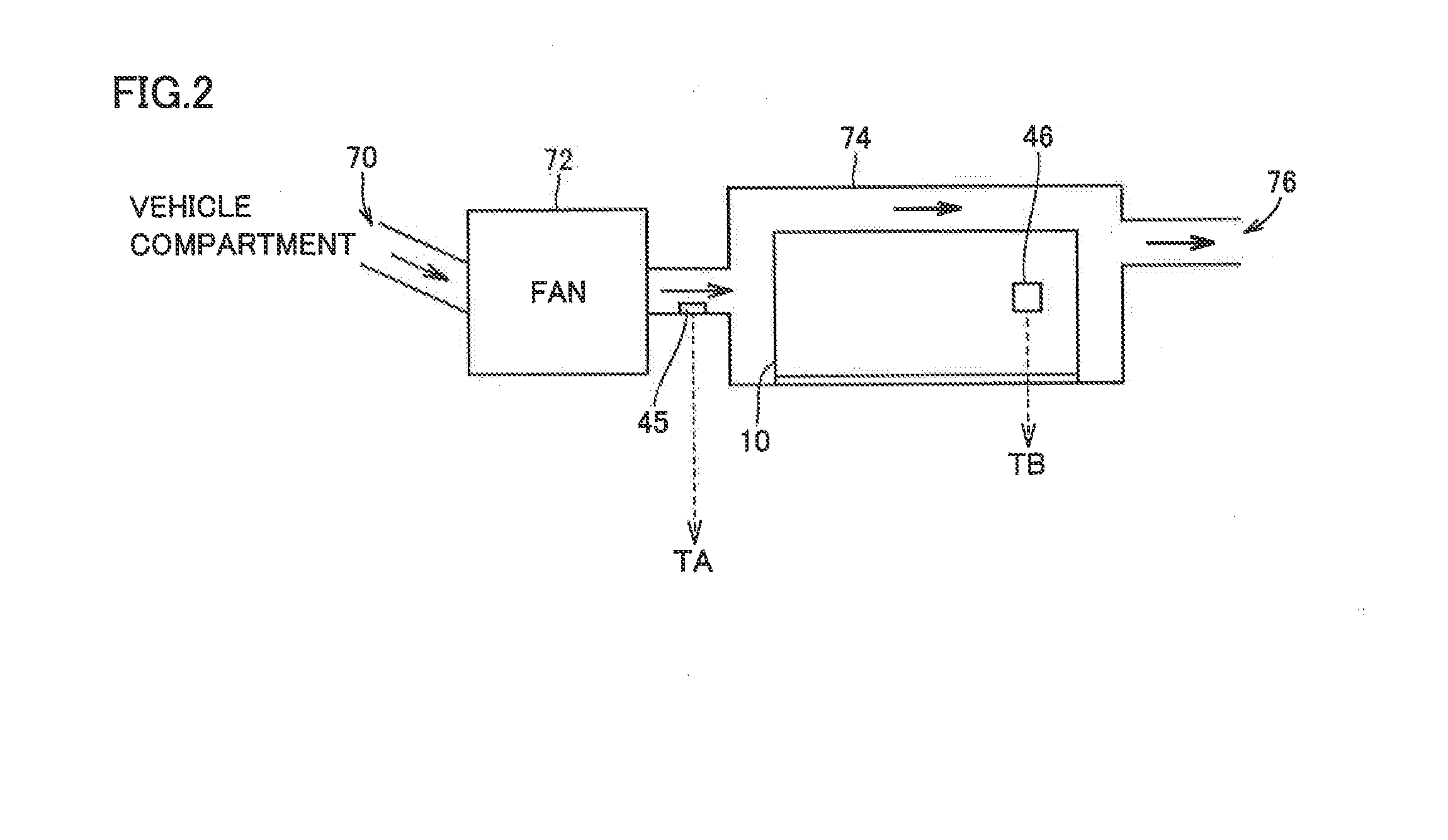
[0031]Referring to FIG. 1, an electric powered vehicle 100 includes a battery 10, an inverter 20, a motor generator 30, and a driving wheel 35. Electric powered vehicle 100 further includes a voltage sensor 42, a current sensor 44, a temperature sensor 46, a wheel speed sensor 37, an electric control unit (ECU) 50, a display device 60, a navigation device 6, an intake air temperature sensor 45, and a charger 4. Intake air temperature sensor 45 measures the intake air temperature of the cooling device that cools battery 10, as will be described afterwards with reference to FIG. 2.

[0032]Battery 10 is a DC power supply storing the electric power for the vehicle to run. Battery 10 is formed of a secondary battery such as a nickel-metal hydride battery, a lithium ion battery, or the like. Battery 10 is charged by a power supply external to the vehicle by means of cha...

second embodiment

[0062]FIG. 6 is a flowchart to describe the process in the charging method executed in the second embodiment. In the second embodiment, rising temperature ΔT1 is set based on a difference ΔSOC between a full-charge amount and the current amount of charge, in addition to the temperature difference ΔT between limitation start temperature Tlim and battery temperature TB in rapid charging, to determine the charging rate for rapid charging.

[0063]Referring to FIG. 6, upon initiation of the process, the current battery temperature TB and intake air temperature TA are obtained at step S11. At step S12, the current battery temperature TB is subtracted from the limitation start temperature Tlim, as in the following equation (1) to obtain temperature difference ΔT, similar to the first embodiment.

ΔT=Tlim−TB  (1)

[0064]At step S13, the current SOC of battery 10 is obtained. SOC is detected by a known method based on the accumulated value of current IB and / or voltage VB.

[0065]At step S14, the amo...

third embodiment

[0078]FIG. 8 is a flowchart to describe the process in the charging method executed in the third embodiment. In the third embodiment, the possible increasing temperature is set based on a temperature difference ΔT between limitation start temperature Tlim and battery temperature TB in rapid charging to determine the charging rate for rapid charging. At this stage, a temperature increase expected value ΔT2 in vehicle-running is set variable based on the running destination information, as well as information of the average current during the previous running operation, and the like to determine whether to limit the charging rate or not.

[0079]Referring to FIG. 8, upon initiation of the process, the current battery temperature TB is obtained at step S21. At step S22, the current battery temperature TB is subtracted from the limitation start temperature Tlim to obtain temperature difference ΔT, as in the following equation (1), likewise with the first and second embodiments.

ΔT=Tlim−TB  ...


PUM


Abstract

A charging device for charging a battery (10) by an external power supply (2) includes a temperature sensor (46) for detecting the temperature of the battery, a charger (4) receiving electric power from the external power supply to charge the battery, and a control device (50) controlling the charger such that the battery is charged at a charging rate determined based on the temperature difference between a charging / discharging limitation start temperature and the battery temperature. Preferably, the control device (50) determines the charging rate based on the difference between the amount of charge corresponding to full charge of the battery (10) and the current remaining amount of charge, and the temperature difference. Preferably, the vehicle (100) on which the battery (10) is mounted repeatedly carries out charging and vehicle-running. The control device (50) determines the charging rate according to the temperature increase expected amount when the vehicle runs next time.

Description

CROSS-REFERENCE TO RELATED APPLICATIONS[0001]This application is a national phase application of International Application No. PCT / JP2011 / 059902, filed Apr. 22, 2011, the content of which is incorporated herein by reference.TECHNICAL FIELD[0002]The present invention relates to a charging device and charging method for a vehicle-mounted battery, particularly to a charging device and a charging method for charging a vehicle-mounted battery by an external power supply.BACKGROUND ART[0003]In recent years, electric vehicles and hybrid vehicles are attracting attention as environment-friendly vehicles. An electric vehicle has a vehicle-mounted battery charged from an external source. Furthermore, research efforts are now being made to allow a vehicle-mounted battery to be charged from an external source in some hybrid vehicles.[0004]When a vehicle-mounted battery is to be charged from an external source, the time required for charging becomes an issue. Charging must be carried out with hi...

Claims


Application Information

Patent Timeline
Patent Type & Authority Applications(United States)
IPC IPC(8): B60L11/18
CPCB60L11/1809H01M10/443H01M10/46Y02T90/14H01M2220/20B60L2260/56Y04S30/14Y02T10/7072B60L53/20B60L53/665B60L53/11B60L58/24H02J7/007194Y02T10/70Y02T90/12Y02T90/167Y02E60/10H02J7/04
Inventor HIROE, YOSHIHIKO
Owner TOYOTA JIDOSHA KK
Why Eureka
Try Eureka