
Optical detection system

a detection system and optical technology, applied in the field of optical detection systems, can solve problems such as trouble, affecting business reputation, and restitution, and achieve the effects of accurate compensation of wavelength response differences, efficient detection, and reduced industrial production costs

Inactive Publication Date: 2014-02-13
CHROMA ATE
View PDF5 Cites 3 Cited by
  • Summary
  • Abstract
  • Description
  • Claims
  • Application Information

AI Technical Summary

Benefits of technology

The invention provides an optical detection system that can compensate for differences in wavelength response among optical detection modules, resulting in improved detection quality and consistent data. This system can efficiently finish detection and reduce production costs, while ensuring accurate imaging quality of display devices. The invention aims to achieve consistent luminous intensity and imaging chromaticity in each region of the display device.

Problems solved by technology

However, with the mass production in factories, there are also increasing probabilities for defects caused by unexpected factors of human error and process error, such as non-uniform display brightness, saturation and other problems of optical characteristics, which hinder the assurance of product quality.
If the defective products with serious defects are delivered to the consumers or suppliers, it will result in refund trouble, and even affect the business reputation.
Consequently, either poor detection quality or slow detection speed will burden the operation of the production line, finally affecting the product delivery.
In case of the above detection efficiency problems, it will not only affect the delivery time, but also decrease the market competitiveness of the products.
Even if the product's functions are superior to its counterparts on the market, it will not be successful in the end.
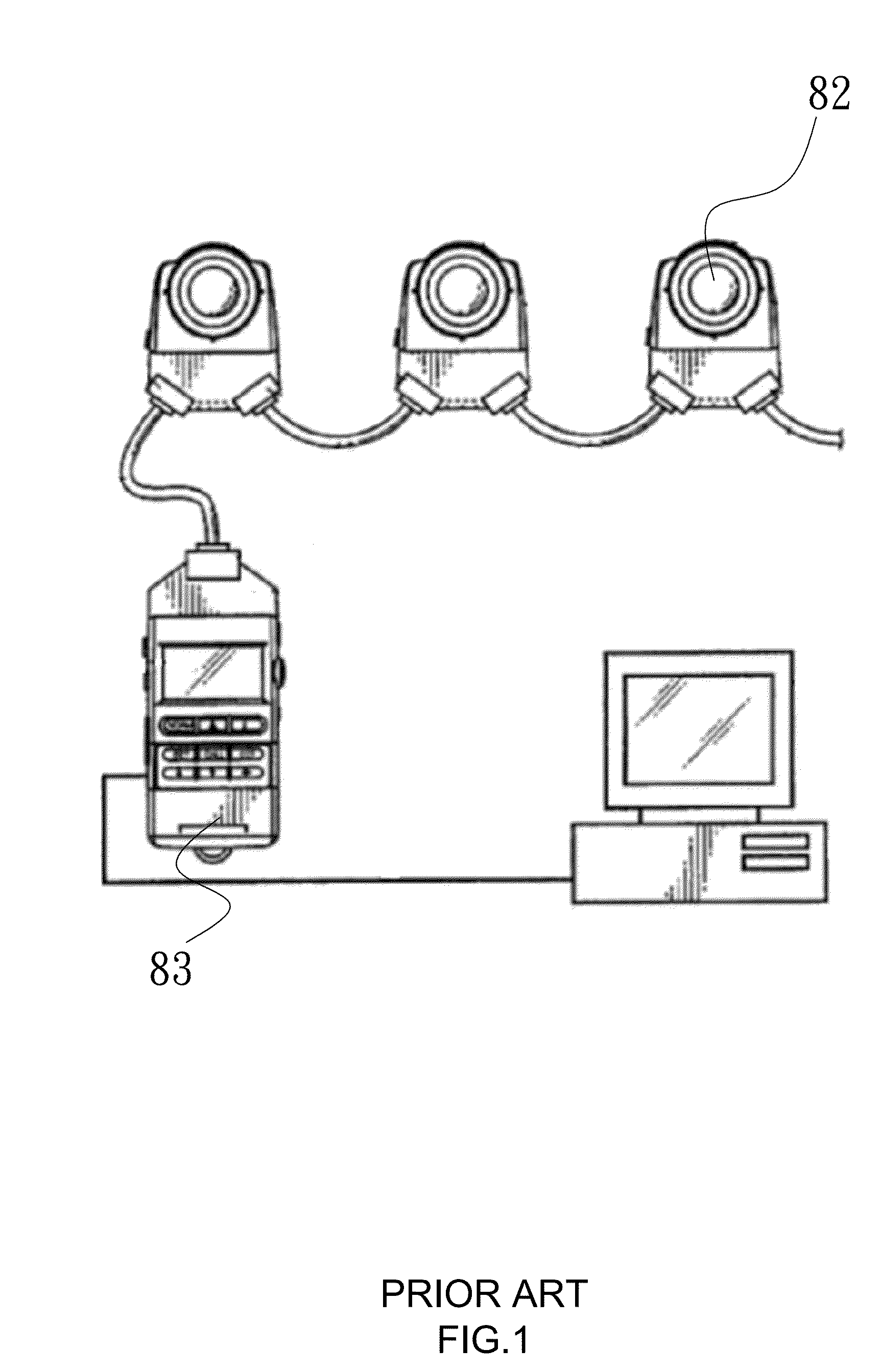
However, a spectrophotometer is fairly expensive and the test is time-consuming.
However, it only provides a single measurement value, rather than performing measurement under respective wavelengths.
Thus, it fails to reflect the optical characteristics of the display device or projector 82 correctly and completely.
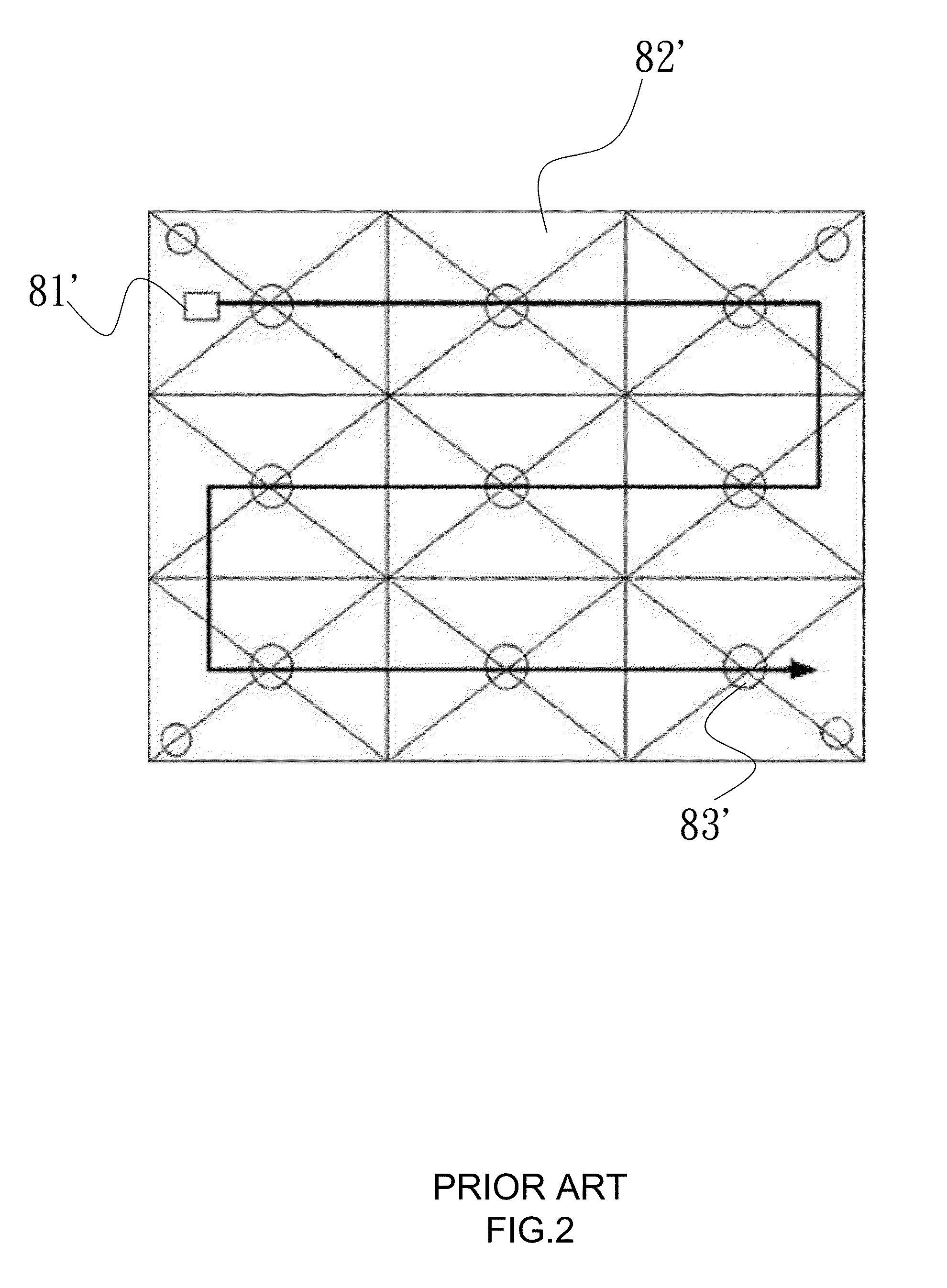
However, due to the slow measurement speed of spectrophotometer 81′, and nine repeated measurements in total, it increases the overall measurement time.
Therefore, it is commercially impractical.
However, this structure increases the cost greatly and does not have market competitiveness.
However, this calibration is only applicable to the uniform light source which has slight chromaticity difference of the luminance at each point.
In case the great chromaticity difference exists in the luminance of the target light source, this calibration method will result in a significant error.
Consequently, for the light sources with poor white balance, such as those rich in red or blue, the conventional system will be interfered by the wavelength response difference of the individual luminance meters and the compensation error of the fixed calibration coefficients.
As a result, the final measurement results will be inconsistent with the actual situation, and the operator of the system will obtain wrong results.

Method used


Image

  • Optical detection system
  • Optical detection system
  • Optical detection system

Examples


Embodiment Construction

[0035]The aforementioned and other technical contents, aspects and effects in relation with the invention can be clearly appreciated through the detailed descriptions concerning the preferred embodiments of the invention in conjunction with the appended drawings.

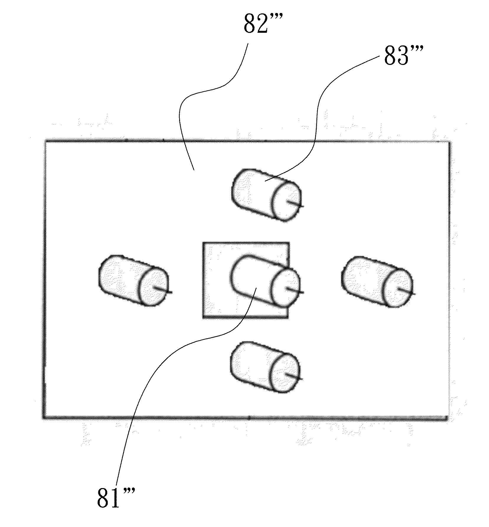
[0036]FIGS. 5 and 6 are schematic diagrams of an optical detection system disclosed in the invention. For the purpose of illustration, the system is used to detect the luminous intensity or reflex intensity of a display device 9. Put it simply, it is to detect the optical characteristics of light source 91 of the display device 9, including brightness, luminance, chromaticity and so on. In this way, the complete optical display information of the display device 9 can be detected. The display device 9 described herein is intended to encompass all types of display panels and projection devices known in the art.

[0037]The display device 9 includes a light source 91 and a predetermined display range 92. The predetermined display ...


PUM


Abstract

The invention relates to an optical detection system for detecting the optical distribution of a display device having a light source and a predetermined display range divided into multiple virtual detection regions. The system includes a power module for supplying power to the light source, a monochromatic module for detecting luminous intensity of the light source at various wavelengths within a selected virtual detection region, multiple optical sensor modules, each corresponding to one of the virtual detection regions, a memory module saving wavelength correction parameters of the optical sensor modules, and a processor module receiving the wavelength distribution within the selected virtual detection region of the display device, and for calculating and compensating for expected detection values of the respective optical sensor modules based on the wavelength correction parameters and actual detection values of the optical sensor modules.

Description

FIELD OF THE INVENTION[0001]The present invention relates to an optical detection system and, more particularly, to an optical detection system for rapid and accurate detection of the optical imaging characteristics (chromaticity, brightness, luminance, etc.).DESCRIPTION OF THE RELATED ART[0002]With the continued development of modern technology, and the higher demands of modern people towards life quality, more and more video devices have come into being. For example, the LED backlight LCD display or television has become an indispensible appliance to many families. Moreover, the projector with high-pressure discharge lamp, or portable LED projector takes another consumer group as the target. It is quite important for the users who need to transmit information through meetings, briefings or teaching sessions. Thus, the targets for this type mainly include companies, schools or governmental institutions. In addition, the home theater or projector also has its share in the market.[00...

Claims


Application Information

Patent Timeline
Patent Type & Authority Applications(United States)
IPC IPC(8): G09G5/10
CPCG09G5/10G09G3/006G01J3/506G01J1/0488G01J1/4228G01J1/0266G09G3/3413G09G2320/0693G09G2360/145G09G3/3406
Inventor PAN, DING-HSIANGSUNG, HSIN-YUEHOU, TSUNG-HSIENLIN, YU-HSUAN
Owner CHROMA ATE
Learn More