Providing service address space for diagnostics collection

a technology for diagnostics and address space, applied in the direction of error detection/correction, input/output to record carriers, instruments, etc., can solve the problems of further system dumps, significant delay to other processes within the system, and the knock-on effect of these dump delays can be very serious

Inactive Publication Date: 2014-02-13
IBM CORP
View PDF8 Cites 10 Cited by
  • Summary
  • Abstract
  • Description
  • Claims
  • Application Information

AI Technical Summary

Benefits of technology

[0007]According to a first aspect of the present invention there is provided a method for providing service address space for diagnostics collection, comprising: providing a service co-processor attached to a main processor, wherein the service co-processor maintains an independent copy of the main processor's address space in the form of a service address space; updating the service address space by receiving storage update packets from the main processor and applying these to the service address space. The method may include: delegating collection of diagnostic data to the service co-processor by sending a collection command from the main processor to the service co-processor for collection of data from the service address space. The method may also include, at the main processor: monitoring for instructions that modify the main processor's address space; and generating storage update packets; sending the storage update packets on an instruction pipe to the service co-processor. The method may further include, at the service co-processor: monitoring an instruction pipe for storage update packets; and applying the storage update packets to the service address space. The service address space may be initialized by copying the main address space. The method may further include: queuing storage update packets in an instruction pipe from the main processor to the service co-processor such that the service co-processor runs behind the main processor; wherein the service address space contains an historical copy of the main address space. A storage update packet may include: a storage address to be updated; a new value of storage to be updated; and associated information including a system clock value. A collection command may be prioritized over a storage update instruction at the service co-processor. The collection command may be received over a command pipe from the main processor. The collection of diagnostic data may be instructed at an immediate time or at a given time value. The method may additionally include: receiving a collection command with a given time value; and actioning the collection command at the service co-processor when a storage update packet pertaining to the time value is processed. The collection of diagnostic data may include one or more of the group of: a system dump, a system trace, the collection of monitoring and statistics data. After carrying out a collection of diagnostic data, the service co-processor may: reset the service address space by copying the contents of the main address space to the service address space and re-starting the process of mirroring all storage updates to the service co-processor. The method may further include: enabling direct access to the service address registers of the service co-processor for analysis.
[0008]According to a second aspect of the present invention, a system for providing service address space for diagnostics collection, comprises: a service co-processor attached to a main processor, wherein the service co-processor maintains an independent copy of the main processor's address space in the form of a service address space; a storage update receiving component for updating the service address space by receiving storage update packets from the main processor and applying these to the service address space. The system may include an instruction pipe between the main processor and the service co-processor. The main processor may include: a service delegation component for delegating collection of diagnostic data to the co-processor by sending a collection command from the main processor to the service co-processor for collection of data from the service address space. The system may also include a command pipe between the main processor and the service co-processor. The system may include: a service address space initializing or resetting component at the service co-processor for initializing or resetting the service address space by copying the main address space. The service co-processor may run asynchronously to the main processor with storage update packets queued in an instruction pipe. In one embodiment, the service co-processor may be integrated into a system with a main processor. In another embodiment, the service co-processor may be a stand-alone system for attachment to a main processor by a high-speed link.

Problems solved by technology

However, a system dump is a time-consuming process that causes a significant delay to other processes within the system.
In a busy production environment this dump delay can cause numerous secondary problems, such as tasks timing-out and themselves abnormally ending (ABENDing) causing further system dumps to be generated or carried out, and work backing-up to the point where the system becomes overloaded.
The knock-on effect of these dump delays can be very serious, often more serious than the problem for which the dump was originally carried out.
In extreme cases, the system may not recover back to a normal running state without a complete system reset.
The dump delays may also cause the system to appear unresponsive to the end-user, and the build-up of unprocessed work may prevent new work from being accepted.
Due to the problems described, it is common practice for customers to disable certain system dumps from being carried out at all, so that critical diagnostic information is lost.
All these problems lead to reduced customer satisfaction and increased service costs.
In addition to system dumps, other diagnostic tools are limited by the current machine architecture because of the performance overhead of employing them.
The performance overhead of taking such trace records often means it is not viable to run with full tracing enabled in a production system, such that once again, vital diagnostics are lost if a failure occurs and problem determination is required.

Method used


Image

  • Providing service address space for diagnostics collection
  • Providing service address space for diagnostics collection
  • Providing service address space for diagnostics collection

Examples


example

[0054]An example of a simple computer system as described above may be a safety-critical control system in a car, such as a ‘brake-by-wire’ controller, which might need to take a diagnostic dump whilst still providing full braking function. Such a system cannot afford to ‘freeze-up’ while it processes a system dump.

[0055]A brake-by-wire system in a car replaces traditional components such as the pumps, cylinders and belts with electronic sensors and actuators controlled by software. The safety critical nature of such systems means they have not been widely implemented in automobiles.

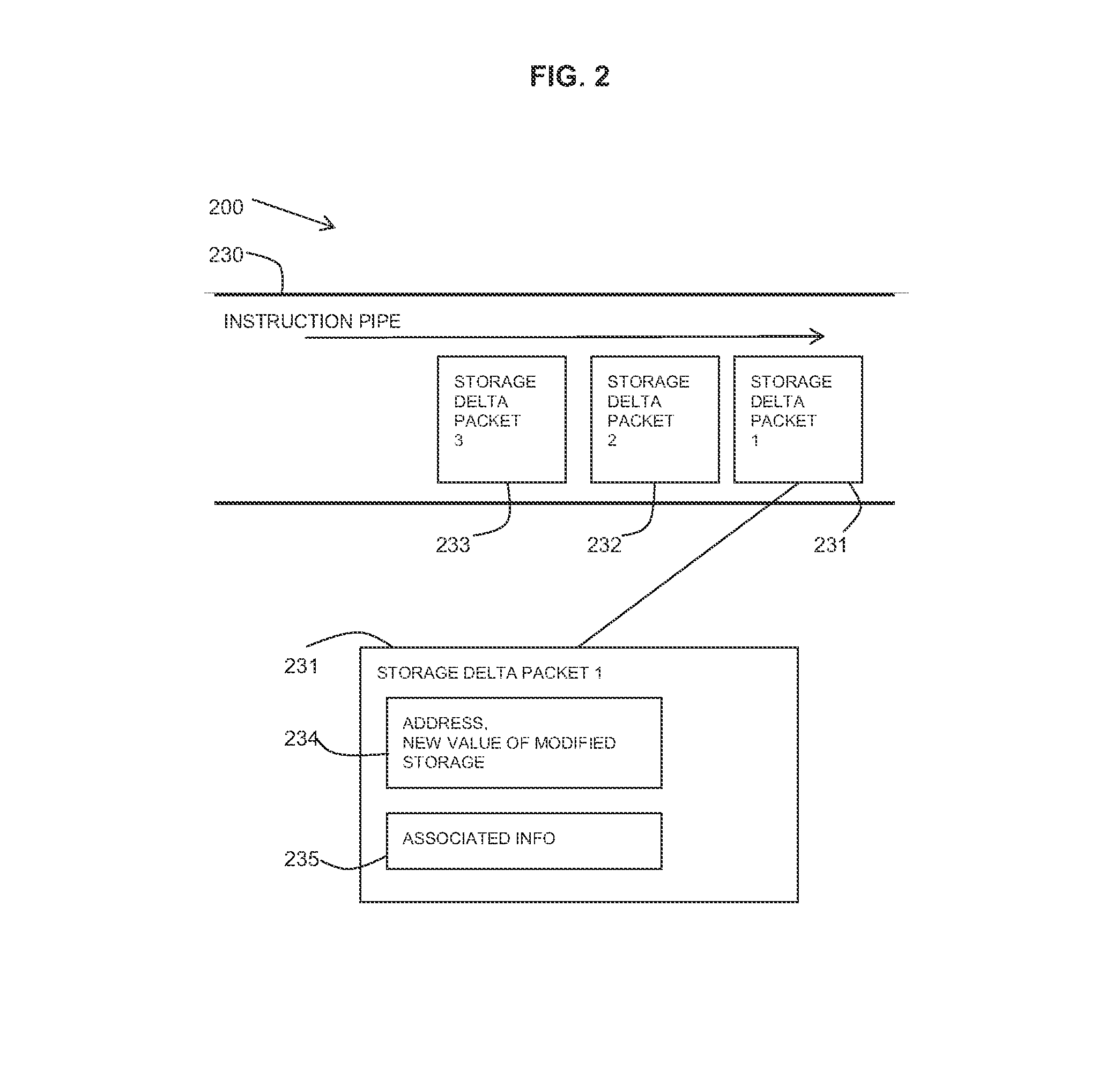
[0056]The storage update packet for such a system could look like this:[0057]System clock value;[0058]Address of updated storage;[0059]Length of updated storage;[0060]Value of updated storage.

[0061]This storage update packet may consist of fixed length fields for the system clock value, address and length of the updated storage, and a variable length field to contain the new value of the updated storage....


PUM


Abstract

A method and system are provided for providing a service address space for diagnostics collection. The system includes: a service co-processor attached to a main processor, wherein the service co-processor maintains an independent copy of the main processor's address space in the form of a service address space; and a storage update receiving component for updating the service address space by receiving storage update packets from the main processor and applying these to the service address space. An instruction pipe may be provided between the main processor and the service co-processor. The main processor may include: a service delegation component for delegating collection of diagnostic data to the co-processor by sending a collection command from the main processor to the service co-processor for collection of data from the service address space.

Description

BACKGROUND[0001]Computing systems require memory in order to function. This computer memory is referenced by address and the full range of memory available to the system is known as the address space. When a problem with a computer system is being investigated the contents of this address space is of vital importance as it shows the state of the processes within the system.[0002]In order to access the contents of the address space for diagnostic purposes a system dump can be generated or carried out. However, a system dump is a time-consuming process that causes a significant delay to other processes within the system.[0003]In a busy production environment this dump delay can cause numerous secondary problems, such as tasks timing-out and themselves abnormally ending (ABENDing) causing further system dumps to be generated or carried out, and work backing-up to the point where the system becomes overloaded. The knock-on effect of these dump delays can be very serious, often more seri...

Claims


Application Information

Patent Timeline
Patent Type & Authority Applications(United States)
IPC IPC(8): G06F3/06
CPCG06F3/065G06F11/0724G06F11/0778G06F11/3648G06F11/34G06F12/0615G06F12/0842G06F11/3476G06F3/0619G06F3/0659G06F3/067G06F9/3867G06F12/063G06F2212/1032
Inventor HARMAN, DAVID J.LEEDHAM, NEIL W.WALSH, KIM P.WRIGHT, ANDREW
Owner IBM CORP
Why Eureka
Try Eureka