Displacement Sensor, Displacement Detecting Device, and Operation Device

a displacement sensor and displacement technology, applied in the direction of electrical/magnetically converting sensor output, generator/motor, instruments, etc., can solve the problems of complex configuration of displacement sensors, inability to detect displacement in the positive direction and displacement in the negative direction, and achieve simple and thin structure, efficient, accurate, reliable detection

Active Publication Date: 2014-02-20
MURATA MFG CO LTD
View PDF8 Cites 56 Cited by
  • Summary
  • Abstract
  • Description
  • Claims
  • Application Information

AI Technical Summary

Benefits of technology

[0064]According to the present invention, with the simple and thin structure, a displacement desired to be detected such as a bending or a twist can be efficiently, accurately, and reliably detected without depending on measurement temperature.

Problems solved by technology

However, as described also in the Patent Literature 1, in the displacement sensor using PVDF, since PVDF has pyroelectricity, a structure in which temperature change does not occur in PVDF at the time of measurement has to be built, so that the configuration of the displacement sensor is complicated.
There is consequently a problem such that, for example, a twist in which a displacement in the positive direction and a displacement in the negative direction exist cannot be detected by a single film.

Method used


Image

  • Displacement Sensor, Displacement Detecting Device, and Operation Device
  • Displacement Sensor, Displacement Detecting Device, and Operation Device
  • Displacement Sensor, Displacement Detecting Device, and Operation Device

Examples


first embodiment

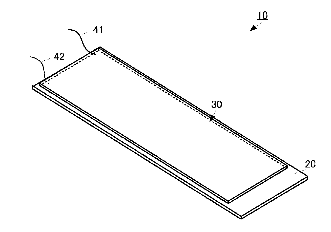
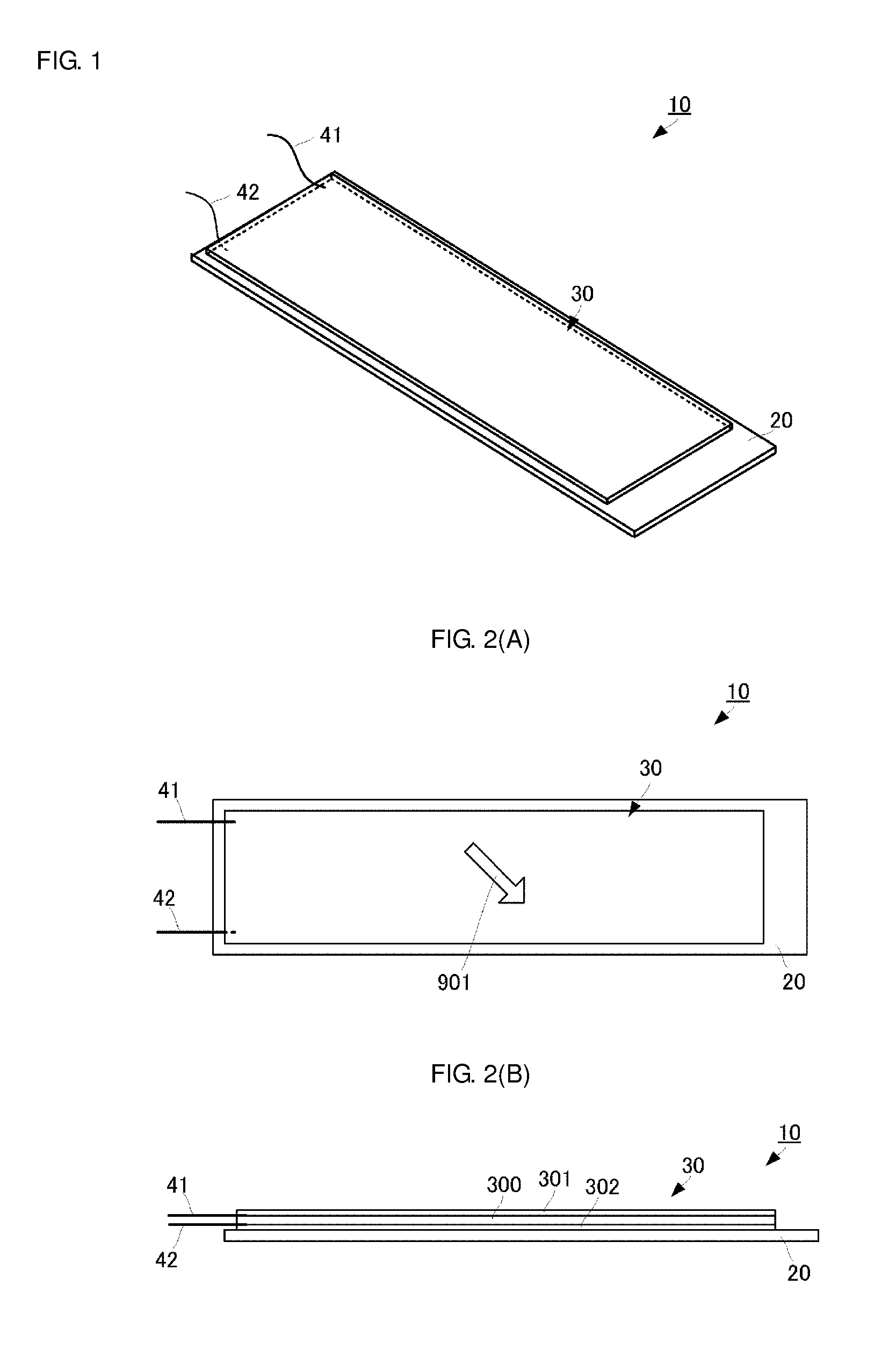
[0091]A displacement sensor according to the present invention will be described with reference to the drawings. FIG. 1 is an appearance perspective view of a displacement sensor 10 of the embodiment. FIGS. 2A and 2B are a plan view and a side view, respectively, of the displacement sensor 10. FIG. 2B is a side view in which the long-side direction of the displacement sensor 10 corresponds to the lateral direction of the diagram (an end face of the short-side direction is viewed).

[0092]The displacement sensor 10 has an elastic member 20 having a flat plate shape and a piezoelectric element 30 in a flat film shape. The elastic member 20 has predetermined thickness and, in plan view, a rectangular shape having long and short directions, which is long in one direction and short in a direction perpendicular to the direction. The elastic member 20 is made of polymer having relatively high strength such as polyethylene terephthalate (PET) or acrylic resin (PMMA). In this case, preferably,...

second embodiment

[0129]A piezoelectric sheet 330 is attached to the first main face of the elastic member 21. The piezoelectric sheet 330 has the same material, the same shape, and the same uniaxial stretch direction as those of the piezoelectric sheet 310 of the An electrode 331 is formed on a surface opposed to the elastic member 21 of the piezoelectric sheet 330. The external connection terminal 41A is connected to the electrode 331. By the piezoelectric sheet 330 and the electrode 331 and the conductive elastic member 21 disposed while sandwiching the piezoelectric sheet 330, a third piezoelectric element 33 (corresponding to a first flat-film-shaped piezoelectric element of the present invention) is constructed.

[0130]A piezoelectric sheet 340 is attached to the second main face opposed to the first main face of the elastic member 21. The piezoelectric sheet 340 has the same material, the same shape, and the same uniaxial stretch direction as those of the piezoelectric sheet 320 of the second e...

third embodiment

[0146]To the embodiment, the configuration of commonly using the electrode on the elastic member side described in the third embodiment can be also employed. In this case, the thin-type displacement sensor having a simplified configuration, resistive to noise due to external factors and capable of simultaneously detecting a bending and a twist can be realized.

[0147]Further, in the case of detecting only a twist as illustrated in FIGS. 10A and 10B, it is sufficient to form only the sixth piezoelectric element 36 in the elastic member 20.

[0148]In the configuration of disposing the piezoelectric elements for detecting displacements in the same direction on both main faces of the elastic member described in the second embodiment and the configuration of disposing the piezoelectric elements for detecting displacements in different directions on both main faces of the elastic member described in the fourth embodiment, when the strengths of the piezoelectric elements disposed on both main ...


PUM


Abstract

A displacement sensor having a rectangular shaped elastic member. A piezoelectric element is attached to a first main face of the elastic member. The piezoelectric element has a rectangular-shaped piezoelectric sheet and electrodes on both main faces of the piezoelectric sheet. The piezoelectric sheet is made of poly-L-lactic acid and is at least uniaxially-stretched. The piezoelectric element is attached so that the uniaxial-stretching direction of the piezoelectric sheet is 45° relative to a long-side direction of the elastic member. When the elastic member is bent along the long-side direction, the piezoelectric sheet is stretched along the long-side direction, and the piezoelectric element generates voltage of predetermined level.

Description

CROSS REFERENCE TO RELATED APPLICATIONS[0001]The present application is a continuation of International application No. PCT / JP2012 / 059443, filed Apr. 6, 2012, which claims priority to Japanese Patent Application Nos. 2011-086412, filed Apr. 8, 2011, 2011-101407, filed Apr. 28, 2011, and 2011-106990, filed May 12, 2011, the entire contents of each of which are incorporated herein by reference.FIELD OF THE INVENTION[0002]The present invention relates to a displacement sensor attached to a subject and detecting a bending and a twist in the subject, and a displacement detecting device and an operation device each using the displacement sensor.BACKGROUND OF THE INVENTION[0003]Various displacement sensors for detecting a bending amount or the like of a subject by using a sheet-shaped member having piezoelectricity are devised. For example, Patent Literature 1 describes a sensor for detecting movement of a columnar projection which moves in the vertical directions by pulsation, using polyv...

Claims


Application Information

Patent Timeline
Patent Type & Authority Applications(United States)
IPC IPC(8): H01L41/113
CPCH01L41/1132G01B7/16G01D5/18G01L1/16H10N30/304H10N30/302G01D5/185H10N30/857
Inventor ANDO, MASAMICHIKAWAMURA, HIDEKI
Owner MURATA MFG CO LTD
Why Eureka
Try Eureka