Drill Rig Moving System

a moving system and drilling rig technology, applied in transportation and packaging, earth-moving drilling and mining, vehicles, etc., can solve the problems of increasing friction, vibration, environmental contamination, and time-consuming and difficult movement of drilling rig masts from transport trailers to engagement with substructures, so as to prevent protection from environmental contaminants, reduce friction, and reduce force

Active Publication Date: 2014-02-27
SCHLUMBERGER TECH CORP
View PDF3 Cites 46 Cited by
  • Summary
  • Abstract
  • Description
  • Claims
  • Application Information

AI Technical Summary

Benefits of technology

[0029]A primary advantage of the present invention is that it provides a primary containment volume for the linear slide bearings and an optional lubricant, preventing protection from environmental contaminants, providing a lower friction (lower force) and smoother sliding of the drill rig.
[0030]An advantage of the double cylinder embodiment of the invention is that it provides a highly stable double shaft-mounted assembly. Another advantage of the double cylindrical slide configuration is that it permits a lower assembly height which requires less clearance to the lift cylinder to obtain a desired ground clearance.
[0031]Another advantage of the invention is that the vertical loading distribution over linear sleeve bearings on cylindrical slides is more predictable when distributing over contaminated flat surfaces that are subject to rapid wear and distortion, creating uneven surface high points.
[0032]Another advantage of the invention is that it provides the option to use shafts of non-corrosive, stainless steel, requiring no chrome or other oxidation-resistant coatings or chemicals. Another advantage of the invention is that cylindrical shaft geometry allows use of highly reliable, low friction bushings, and ready access to the best bushing technology.
[0033]Another advantage of the invention is that bushing housing containment of grease using hydraulic cylinder seal-wiper technology maintains pristine shaft surfaces submerged in grease lubrication / bath, greatly reducing bushing and slide wear, and reducing maintenance.
[0034]Another advantage of the invention is that it provides a secondary containment region for the protection of the frictional surface from environmental contaminants. As will be understood by one of ordinary skill in the art, the detailed assemblies and sequence of the steps disclosed may be modified and the same advantageous result obtained.

Problems solved by technology

These locations are often remotely located and in rough terrain.
Movement of rig masts from transport trailers to engagement with substructures remains time consuming and difficult.
However, in conventional land drilling operations, it is necessary to move the rig across natural terrain without minimal disassembly of the drill rig.
The device disclosed in Davidson leaves the rails that comprise the load bearing element and provide longitudinal displacement unprotected and exposed to the elements, which can lead to environmental contamination, increased friction, vibration, increased wear, and reduced life.
The increased frictional load upon the rails eventually degrades horizontal travel performance of the apparatus.
The mechanism utilized by Ricouard poses a number of limitations, namely the rollers that bear the load of the chassis and provide horizontal locomotion of the mechanism are left unprotected and exposed to the elements, which would eventually accumulate contaminants and require maintenance.
Contaminants and other debris present in the working condition of such machinery would also increase the variability of the friction forces opposing horizontal movement.
After passage of time, the lubricated interface may become contaminated due to such exposure, resulting in greater variable coefficient of friction and more difficulty for the horizontal jack to facilitate movement.
As such, the roller assemblies will eventually become worn and obstructed as foreign matter accumulates and grinds against the roller assemblies.
This leads to eventual required maintenance and repair which renders the apparatus unavailable for some time.
In the Patch, Reed and Barnes series of references, the mechanism for bearing the load of the device is by way of a set of rollers, which are not sealed to the elements and may eventually become affected by debris and other materials present in the environment which the devices operate.
As a result of the substantial load being placed upon the rollers, the rollers are susceptible to the additional particulates, which may create additional frictional forces between adjacent rollers.
This leads to more variable coefficient of friction at the roller contact surfaces wherein one load bearing assembly may become more difficult to translate in a horizontal direction, thus adversely affecting the synchronous movement of the entire structure.

Method used


Image

  • Drill Rig Moving System
  • Drill Rig Moving System
  • Drill Rig Moving System

Examples


Embodiment Construction

[0050]The following description is presented to enable any person skilled in the art to make and use the invention, and is provided in the context of a particular application and its requirements. Various modifications to the disclosed embodiments will be readily apparent to those skilled in the art, and the general principles defined herein may be applied to other embodiments and applications without departing from the spirit and scope of the present invention. Thus, the present invention is not intended to be limited to the embodiments shown, but is to be accorded the widest scope consistent with the principles and features disclosed herein.

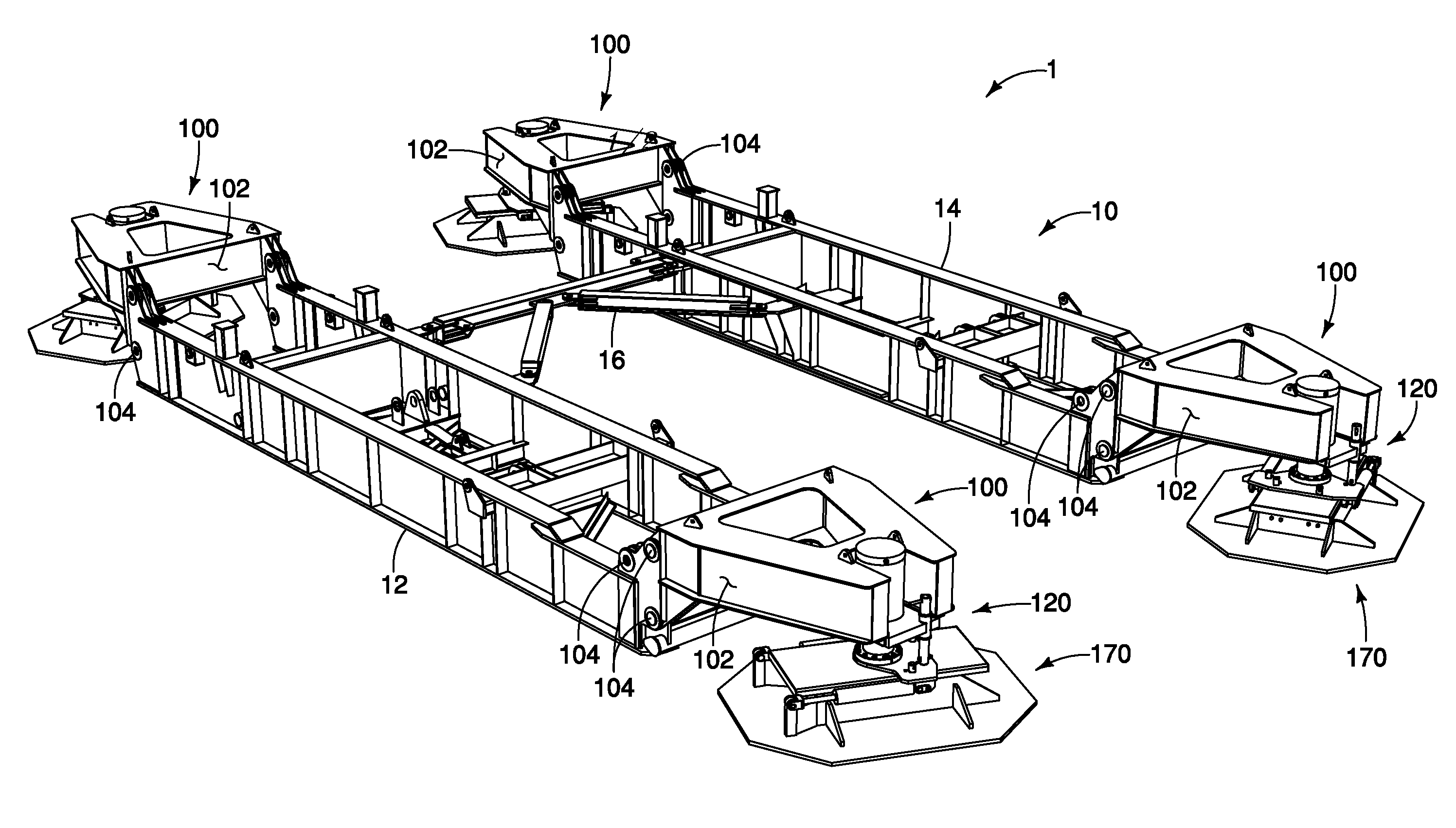
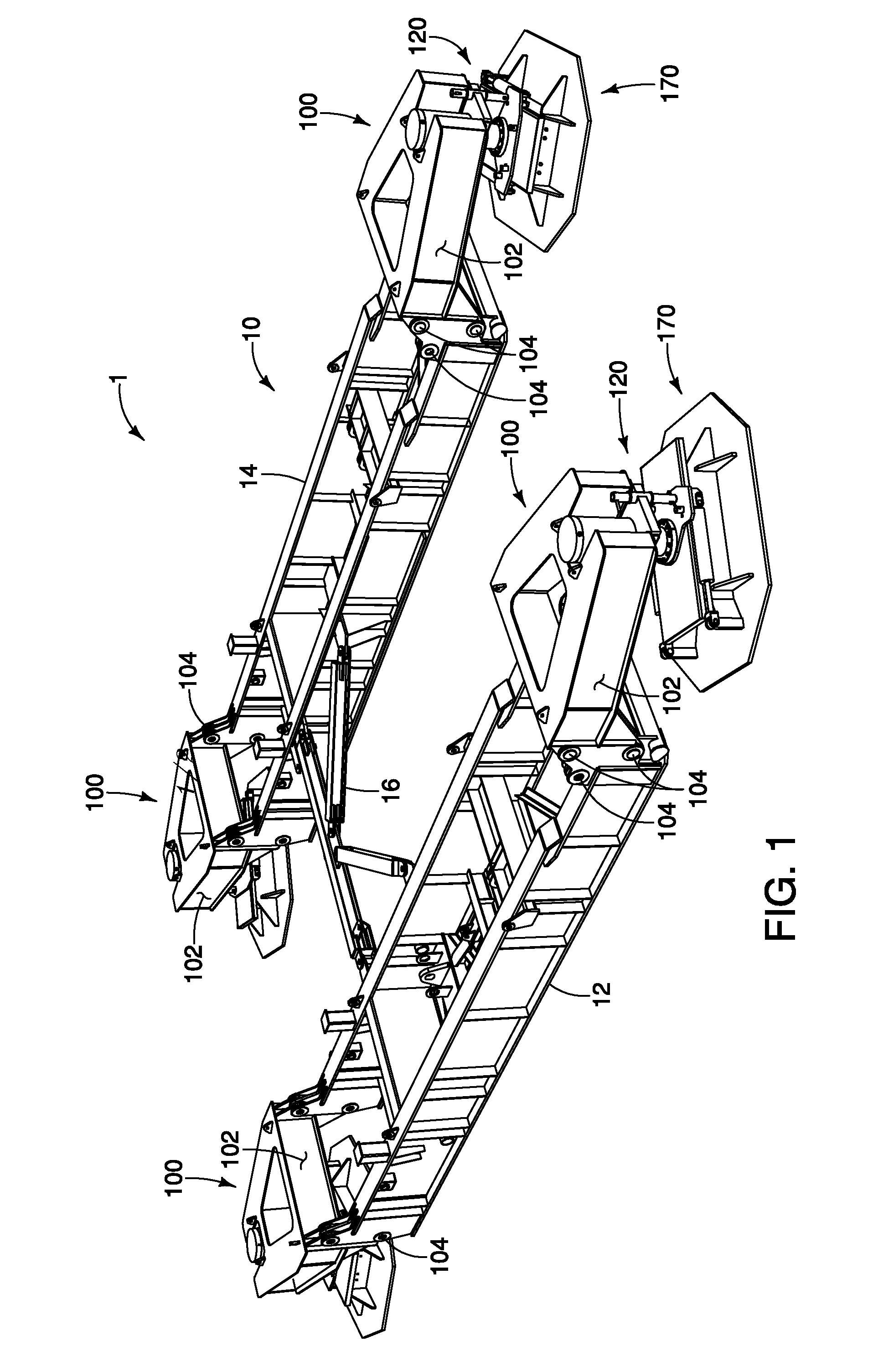
[0051]FIG. 1 is an isometric view of the drill rig moving system 1 having features of the present invention. For visibility, FIG. 1 illustrates only the base box assembly of a drill rig 1. As shown in FIG. 1, a base box assembly 10 includes a driller's side base box 12 and an off-driller's side base box 14 separated by a base box spreader 16. A...


PUM


Abstract

The present invention discloses a drill rig relocation system. Lift frames are provided at opposite ends of a base box of a drill rig substructure. A lift cylinder and bearing mat assembly are rotatably connected beneath the lift frame. The bearing mat assemblies may be rotated to the desired direction for moving the drill rig. The lift cylinders are then expanded, placing the bearing mat assemblies onto the ground and lifting the base boxes and drill rig off the ground. The drill rig is supported on linear sleeve bearings slideably mounted in the bearing mat assemblies. Translation cylinders on the bearing mats expanded to move the rig by translating the linear sleeve bearings along the shafts. After the lift cylinder expands to place the bearing mat on the ground, the translation cylinders are retracted, providing the linear bearing with the full length of the shaft for the next movement.

Description

TECHNICAL FIELD OF INVENTION[0001]The present invention relates to a relocation system for heavy equipment over natural terrain. The invention enables, for example, a drill rig to be self-relocating on property where multiple wellbores are to be drilled within the immediate vicinity. In particular, the invention provides a lift and slide mechanism for which the slide mechanism utilizes linear sleeve bearings engaged on cylindrical slide pairs, where the bearings are located in a primary containment housing that provides a contaminant free environment. The housing can be filled with a lubricant. The result of the design is a significant reduction in the frictional forces resisting the slide movement of the heavy equipment, providing a smoother translation.BACKGROUND OF THE INVENTION[0002]In the exploration of oil, gas and geothermal energy, drilling operations are used to create boreholes, or wells, in the earth. Drill rigs used in subterranean exploration must be transported to the ...

Claims


Application Information

Patent Timeline
Patent Type & Authority Applications(United States)
IPC IPC(8): B62D57/02
CPCB62D57/02E21B15/003E21F13/006
Inventor BRYANT, F. ALLANORGERON, KEITH J.TREVITHICK, MARK W.
Owner SCHLUMBERGER TECH CORP
Why Eureka
Try Eureka