Method of assisting a pilot of a single-engined rotary wing aircraft during a stage of flight in autorotation

a technology of autorotation and pilot assistance, which is applied in the direction of propellers, rotocraft, air transport, etc., can solve the problems of increasing the workload of the pilot of the aircraft, increasing the cost of sinking rate, and increasing the workload of the single-engined aircra

Active Publication Date: 2014-02-27
EUROCOPTER
View PDF3 Cites 44 Cited by
  • Summary
  • Abstract
  • Description
  • Claims
  • Application Information

AI Technical Summary

Benefits of technology

[0028]An object of the present invention is thus to provide a method of assisting a pilot of a single-engined rotary wing aircraft during a stage of flight in autorotation following a failure of the engine of th

Problems solved by technology

Nevertheless, such single-engined aircraft also present drawbacks.
In the event of the single engine being damaged, the power plant, and consequently the single-engined aircraft, presents performance that is degraded, and in the event of the engine failing that can amount to the inability to drive the main rotor and the tail rotor, which leads to a situation that is dangerous, significantly increasing the workload on the pilot of the aircraft.
A stage of flight in autorotation corresponds to a particular stage of flight in which the aircraft flies, descending without any driving power, but at the cost of a sink rate that is rather large.
However, the pilot needs to apply a special piloting procedure and needs to be very attentive firstly to begin by entering into a stage of autorotation when the failure appears, and secondly to continue by performing this always-difficult maneuver all the way to landing.
It is a difficult part of piloting aircraft, in particular single-engined aircraft, and is one of the main reasons for which the flight envelope and the use of an aircraft of this type are reduced.
Likewise, the capacities authorized for single-engined aircraft, such

Method used


Image

  • Method of assisting a pilot of a single-engined rotary wing aircraft during a stage of flight in autorotation
  • Method of assisting a pilot of a single-engined rotary wing aircraft during a stage of flight in autorotation
  • Method of assisting a pilot of a single-engined rotary wing aircraft during a stage of flight in autorotation

Examples


Embodiment Construction

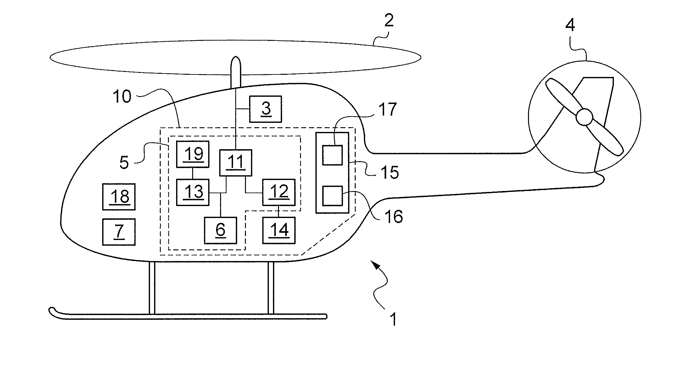
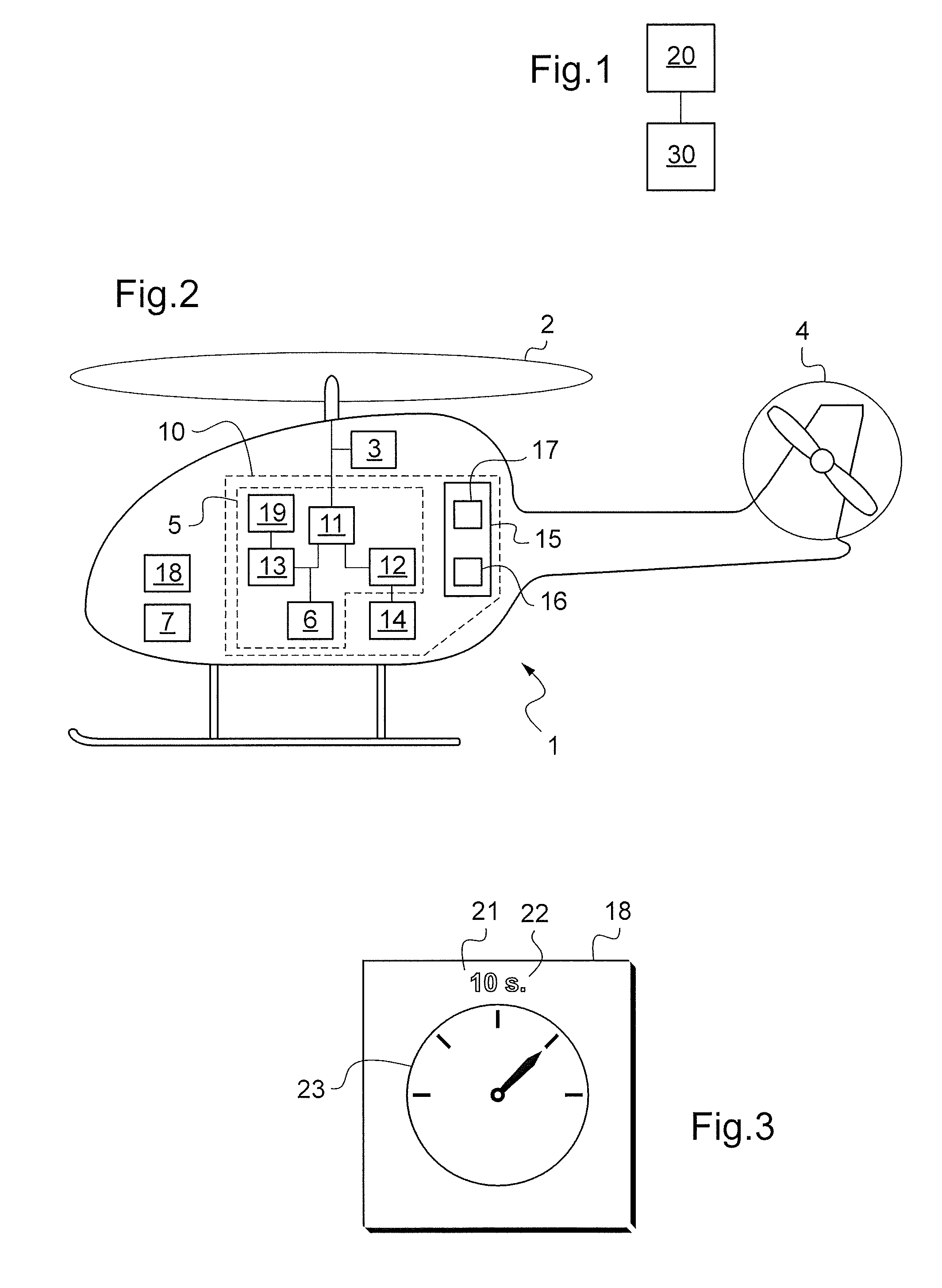
[0130]FIG. 1 shows a method of the invention for assisting a pilot of a rotary wing aircraft 1 during a stage of flight in autorotation. FIG. 2 shows a rotary wing aircraft 1 fitted with a device 10 of the invention for assisting a pilot of the aircraft 1 during a stage of flight in autorotation.

[0131]The method and the device 10 serves to assist the pilot in flying in the event of a failure of the engine of the aircraft 1, in particular in order to reach a stage of flight in autorotation safely and then make a safe landing.

[0132]Such a device 10 of the invention, as shown in FIG. 2, comprises a hybrid power plant 5 fitted with a single engine 13, with an electric machine 12 capable of delivering maximum power Wmax, with a main gearbox (MGB) 11, and with an EECU control unit 19 that delivers the operating characteristics of the engine 13. The device 10 also has electrical energy storage means 14, and control means 15 for controlling the electrical machine 12, which control means inc...


PUM


Abstract

A method of assisting a pilot of a single-engined rotary wing aircraft (1) during a stage of flight in autorotation, said aircraft (1) including a hybrid power plant having an engine (13), an electric machine (12), and a main gearbox (11). Said aircraft (1) also includes electrical energy storage means (14) and a main rotor (2) mechanically connected to said hybrid power plant (5). According to said method, while in flight, the operation of said engine (13) is monitored in order to detect a failure thereof, in particular by monitoring for a drop of power on said main rotor (2), and then in the event of a failure of said engine (13) being detected, said electric machine (12) is controlled to deliver auxiliary power We to said main rotor (2), thereby enabling the pilot of said aircraft (1) to be assisted in maneuvering said aircraft (1) during said stage of flight in autorotation following said failure.

Description

CROSS REFERENCE TO RELATED APPLICATIONS[0001]This application claims priority to French patent application No. FR 12 02304 filed on Aug. 27, 2012, the disclosure of which is incorporated in its entirety by reference herein.BACKGROUND OF THE INVENTION[0002](1) Field of the Invention[0003]The present invention lies in the technical field of power plants for single-engined rotary wing aircraft. The invention relates to a method of assisting a pilot of a single-engined rotary wing aircraft during a stage of flight in autorotation. The invention also provides a single-engined rotary wing aircraft including a device for assisting a pilot of the aircraft during a stage of flight in autorotation.[0004](2) Description of Related Art[0005]A rotary wing aircraft is conventionally provided with at least one main rotor for providing it with lift and possibly also with propulsion, and is generally also provided with a tail rotor, in particular for opposing the yaw torque that is exerted by the ma...

Claims


Application Information

Patent Timeline
IPC IPC(8): B64C27/00
CPCB64C27/006B64C27/14B64D27/24B64D31/00B64D35/02B64D35/08B64D2027/026Y02T50/40Y02T50/60
Inventor CONNAULTE, MATTHIEUMERCIER, CHRISTIANMARIOTTO, DAMIEN
Owner EUROCOPTER
Why Eureka
Try Eureka