
Inductor array chip and dc-dc converter

a technology of array chips and converters, applied in the direction of electric variable regulation, process and machine control, instruments, etc., can solve the problems of inductors array chips, difficult production, and inability to produce, and achieve the effect of easy production and good stability

Inactive Publication Date: 2014-02-27
MURATA MFG CO LTD
View PDF4 Cites 8 Cited by
  • Summary
  • Abstract
  • Description
  • Claims
  • Application Information

AI Technical Summary

Benefits of technology

The present invention provides an inductor array chip that is less likely to have structural flaws during the firing process and is easy to produce with good stability. This invention provides reliable results and ensures the chip's performance is not compromised during production.

Problems solved by technology

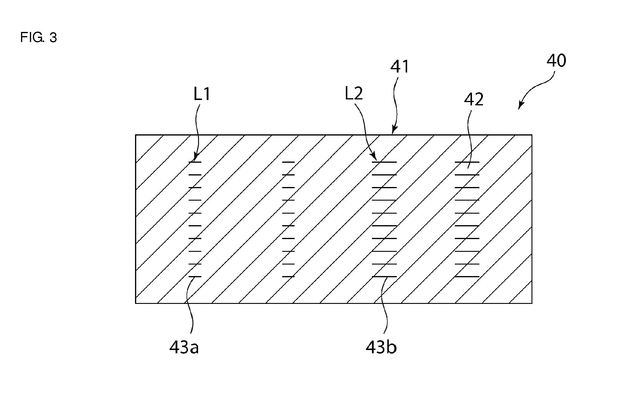
However, in the case where a plurality of types of inductors whose number of stacked coil-shaped conductors differs from one another are arranged within a single inductor chip, a structural defect (a crack or the like) is likely to occur within a magnetic laminated body at the time of firing the inductor chip.
Accordingly, there is a problem in that it is difficult to produce, with good stability, an inductor array chip including a plurality of types of inductors whose number of stacked coil-shaped conductors differs from one another.

Method used


Image

  • Inductor array chip and dc-dc converter
  • Inductor array chip and dc-dc converter
  • Inductor array chip and dc-dc converter

Examples


first preferred embodiment

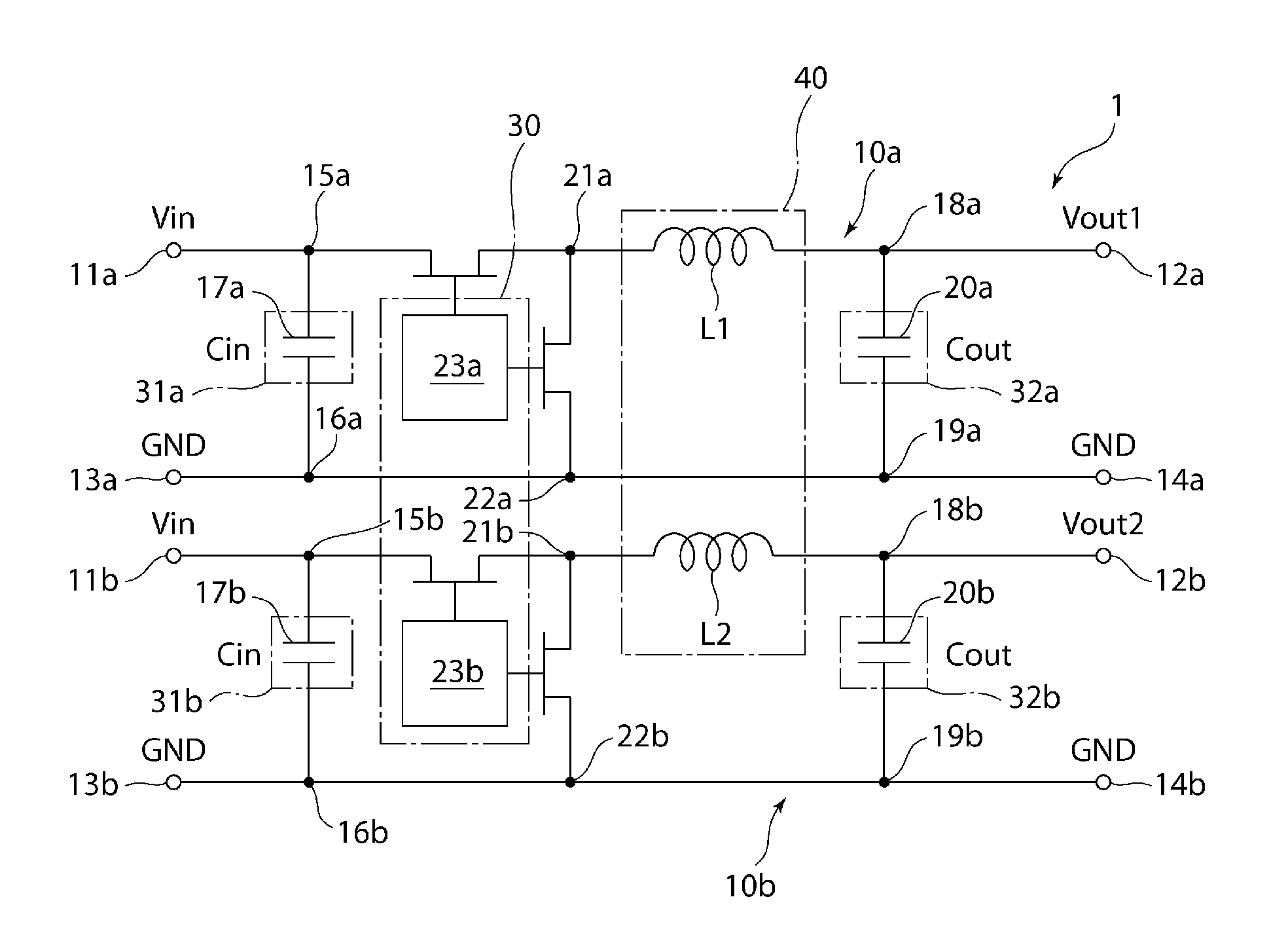
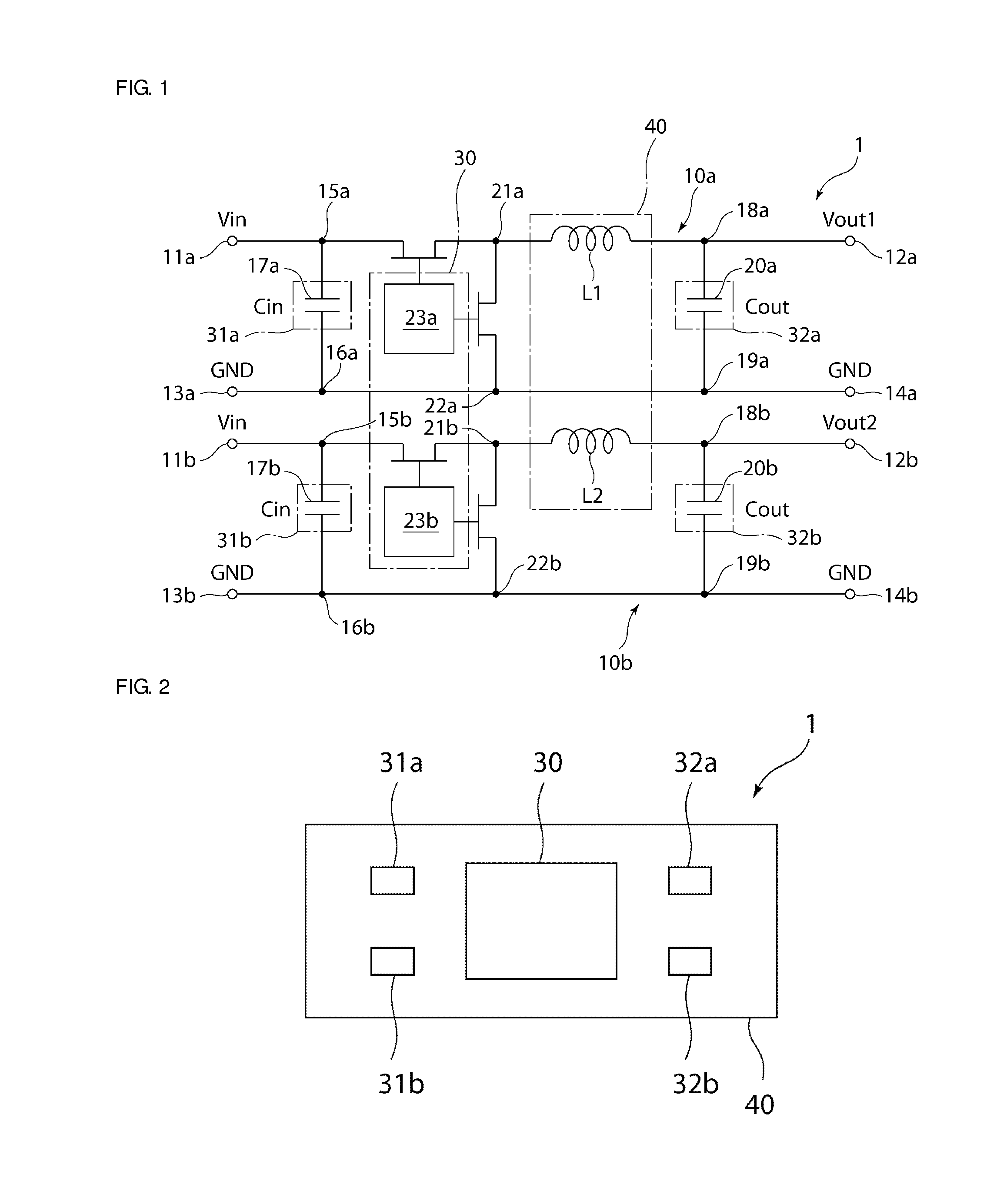
[0030]FIG. 1 is a schematic circuit diagram illustrating a DC-DC converter according to the first preferred embodiment of the present invention. First, the circuit configuration of a DC-DC converter 1 will be explained with reference to FIG. 1.

[0031]The DC-DC converter 1 includes a plurality of converting units. More specifically, the DC-DC converter 1 preferably includes two converting units 10a and 10b. The converting units 10a and 10b may be connected to the same power supply or may be connected to individual power supplies. The output power of the converting unit 10a and the output power of the converting unit 10b are different in at least one of current and voltage. More specifically, in this preferred embodiment, power at the same input voltage Vin is input to each of the converting units 10a and 10b. The converting unit 10a outputs power at a first output voltage Vout1. The converting unit 10b outputs power at a second output voltage Vout2.

[0032]The converting units 10a and 1...


PUM


Abstract

An inductor array chip includes a magnetic laminated body and a plurality of inductors. The magnetic laminated body includes a plurality of stacked magnetic layers. The plurality of inductors are arranged inside the magnetic laminated body. The inductance of a first inductor differs from the inductance of a second inductor. The inductors include a plurality of coil-shaped conductors and via-hole conductors. The plurality of coil-shaped conductors are arranged between the magnetic layers. The via-hole conductors electrically connect the plurality of coil-shaped conductors. The inductors include a plurality of inductors in which the section sizes of the coil-shaped conductors differ from one another.

Description

BACKGROUND OF THE INVENTION[0001]1. Field of the Invention[0002]The present invention relates to an inductor array chip and a DC-DC converter including the inductor array chip.[0003]2. Description of the Related Art[0004]DC-DC converters have been known as elements having a function of outputting power at a voltage different from input power (see, for example, Japanese Patent No. 4325747). A DC-DC converter described in Japanese Patent No. 4325747 includes an inductor chip including inductors, and a control chip and a capacitor chip that are arranged on the inductor chip.[0005]Regarding DC-DC converters, outputting a plurality of types of power, in which at least one of current and voltage differs among the plurality of types of power, from a single DC-DC converter, has been demanded. A DC-DC-converter that meets the above-mentioned demand may include a plurality of converting units. In the case where a plurality of types of converting units in which at least one of the voltage and ...

Claims


Application Information

Patent Timeline
IPC IPC(8): H01F27/28H02M3/158
CPCH02M3/158H01F27/2804H01F2027/2809H02M1/008H01F5/00
Inventor KUBOTA, YOSHIHIRONOMA, TAKASHI
Owner MURATA MFG CO LTD
Learn More