Image restoration method, image restoration apparatus, and image-pickup apparatus

a technology of image restoration and pick-up apparatus, which is applied in the field of image restoration, can solve the problem of not being able to sufficiently deblur the observed image obtained from the optical image formed, and achieve the effect of removing blur

Inactive Publication Date: 2014-02-27
CANON KK
View PDF0 Cites 13 Cited by
  • Summary
  • Abstract
  • Description
  • Claims
  • Application Information

AI Technical Summary

Benefits of technology

[0007]The present invention provides an image restoration method, an image restoration apparatus, and an image-pickup apparatus, which can eliminate...

Problems solved by technology

However, the image restoration methods disclosed in the literatures 1 and 2 address incoherent imaging and c...

Method used


Image

  • Image restoration method, image restoration apparatus, and image-pickup apparatus
  • Image restoration method, image restoration apparatus, and image-pickup apparatus
  • Image restoration method, image restoration apparatus, and image-pickup apparatus

Examples


first embodiment

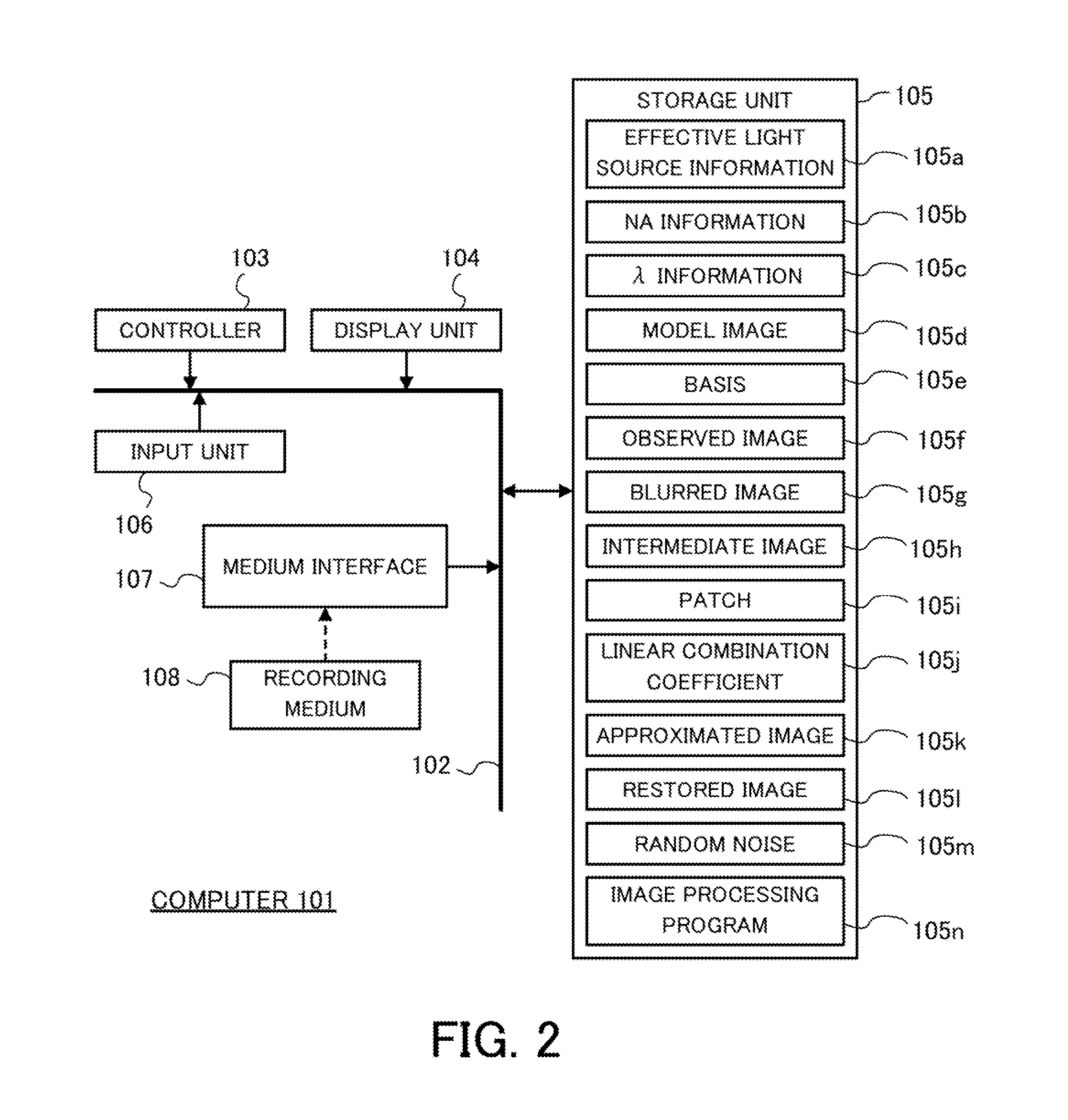
[0066]This embodiment performs for the observed image 105f image processing of removing the noise caused by the image sensor and blur caused by the partially coherent imaging optical system, and obtains the restored image having no noises and no blurs.

[0067]FIG. 5 is a flowchart for explaining a method for generating a blurred image 105g made by removing the noise caused by the image sensor from the observed image 105f.

[0068]Initially, the controller 103 refers to the storage unit 105, performs a partially coherent imaging operation for the model image 105d, generates a blurred model image (S301), and stores the blurred model image in the storage unit 105. Alternatively, a user may store, as the blurred model image in the storage unit 105, an image captured under the same optical condition as the target digital microscope.

[0069]Next, the controller 103 refers to the storage unit 105, generates a blurred basis {b″} (third basis) from the blurred model image (S302), similar to the pr...

second embodiment

[0108]This embodiment also performs for the observed image 105f image processing of removing a noise caused by the image sensor and a blur caused by the partially coherent imaging optical system, and obtains the restored image having no noise and no blur.

[0109]FIG. 8 is a flowchart for explaining a method for generating a blurred image 105g by removing a noise caused by the image sensor from the observed image 105f.

[0110]Initially, the controller 103 refers to the storage unit 105, generates the basis {b} from the model image 105d similar to the processing of S202 (S501), and stores it in the storage unit 105. Each element of the basis {b} is normalized through a division using its L2 norm.

[0111]Next, the controller 103 generates the basis {b′} from the basis {b} similar to the processing of S402 (S502), and stores it in the storage unit 105.

[0112]Next, the controller 103 stores the pixel value generated for each pixel as the artificial random noise n in the random noise 105m of th...


PUM


Abstract

A method includes performing an approximate partially coherent imaging operation for elements of a first basis generated from a model image having no noise and no blur, and generating based upon the first basis a second basis that is blurred, the approximate partially coherent imaging operation being expressed by a convolution integral on an eigenfunction corresponding to a maximum eigenvalue of a Kernel matrix and each element of the first basis, generating an intermediate image in which each pixel value of the observed image that has been denoised is replaced with its square root, and obtaining a restored image by approximating each of a plurality of patches that are set to entirely cover the intermediate image, using a linear combination of elements of the first basis and linear combination coefficients obtained when each patch is approximated by a linear combination of elements of the second basis.

Description

BACKGROUND OF THE INVENTION[0001]1. Field of the Invention[0002]The present invention relates to a restoration (reconstruction) of an image.[0003]2. Description of the Related Art[0004]An observed image obtained by a bright field microscope or a virtual slide including an image sensor (referred to as a “digital microscope” hereinafter) is known as an observed image obtained through a photoelectric conversion of an optical image formed by partially coherent imaging. Conventionally, no methods have been proposed for removing from the observed image a noise caused by the image sensor (which may be simply referred to as a “noise” hereinafter), or a blur caused by an optical system (which may be simply referred to as a “blur” hereinafter). It is a conventionally proposed method to restore an original image by removing the noise and blur from a deteriorated image obtained by photoelectrically converting an optical image formed by incoherent imaging.[0005]For example, Yifei Lou, Andrea L. ...

Claims


Application Information

Patent Timeline
IPC IPC(8): H04N7/18
CPCH04N7/18G02B21/365G06T2207/10056G06T2207/20081G06T2207/30024G06T5/002
Inventor KIMURA, YOSHINORI
Owner CANON KK
Why Eureka
Try Eureka