

Image sensing apparatus
- Summary
- Abstract
- Description
- Claims
- Application Information
AI Technical Summary
Benefits of technology
Problems solved by technology
Method used
Image

Examples
first embodiment
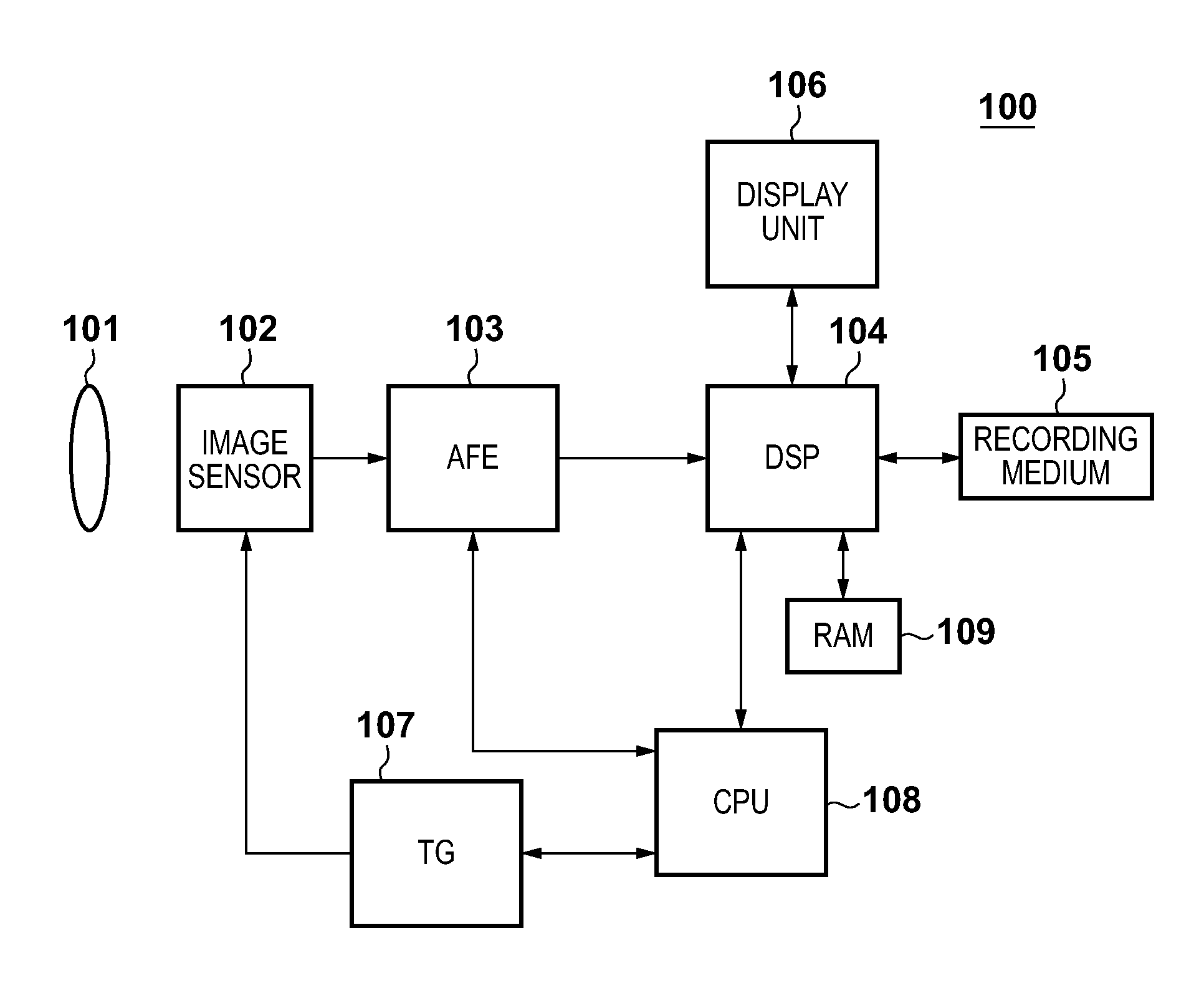
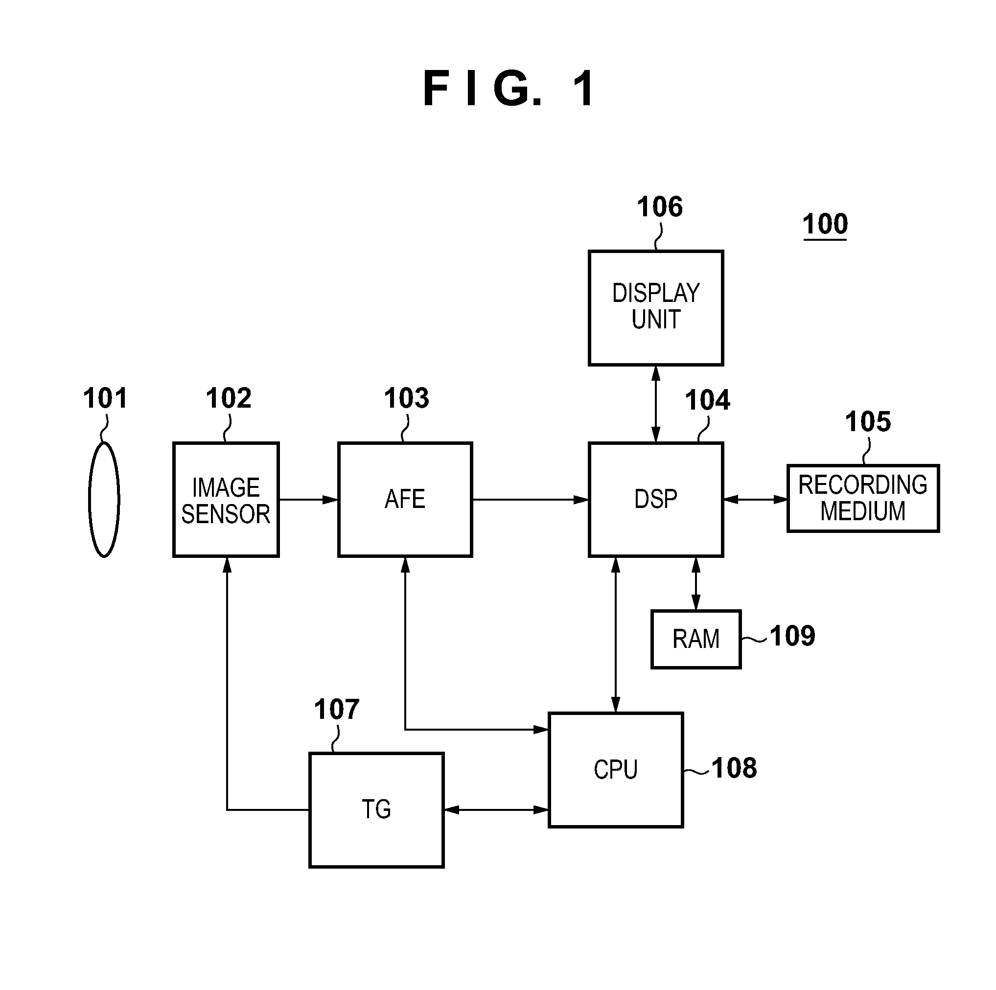
[0034]FIG. 1 is a block diagram showing the overall arrangement of an image sensing apparatus 100 according to the first embodiment of the present invention. An imaging lens 101 images light coming from an object on an image sensor 102. The image sensor 102 photoelectrically converts an object image imaged by the imaging lens 101. In this embodiment, a CMOS image sensor is used as the image sensor 102. The image sensor 102 has a pixel array in which a plurality of pixels are arrayed in matrix. An analog image signal output from the image sensor 102 is converted into a digital signal by an AFE (Analog Front End) 103.
[0035]A DSP (Digital Signal Processor) 104 applies various kinds of image processing, compression / decompression processing, and the like to the digital image signal output from the AFE 103. A recording medium 105 records image data processed by the DSP 104. A display unit 106 displays a sensed image processed by the DSP 104, various menu screens, and the like, and uses a ...
second embodiment
[0070]The first embodiment is premised on that the end of the period HSR is earlier than that of the period S1, as shown in FIG. 6. That is, the output operations of image signals of the (n−1)-th row are complete before completion of write operations of signals of the n-th row in the first light signal holding capacitor 305.
[0071]However, when the number of pixels, signals of which are to be read out from the image sensor 102, is large, the period HSR is prolonged, and the end of the period HSR is often later than that of the period S1. Especially, in a camera having a setting unit which allows the user to set one of a still image mode and moving image mode as an imaging mode, the period HSR often becomes long in the still image mode since all pixels of the image sensor 102 are read out, and it often becomes short in the moving image mode since the number of pixels to be read out is reduced due to decimation or the like. This embodiment will explain a case in which the period HSR ha...
third embodiment
[0078]In the first embodiment, the second light signal transfer switch 311 and second noise signal transfer switch 312 are simultaneously turned on, but they can be turned on at different timings. FIG. 11 is a timing chart in this case. Initially, the signal tn2 is set at High level to execute a signal write operation in the second noise signal holding capacitor 314 after the output of an image signal using the outputs hsr1 to hsrk from the horizontal scanning circuit 402 is complete. Next, the signal ts2 is set at High level to execute a signal write operation in the second light signal holding capacitor 313. FIG. 12 shows a temporal relationship of readout operations. In this case, since the periods N2 and S2 are set at different times, the number of source-follower circuits in the column common readout circuit 300 can be reduced to one, and that source-follower circuit can be shared by the light signal side and the noise signal side.
[0079]FIG. 13 shows the arrangement of the colu...
PUM
 Abstract
Description
Claims
Application Information