Cutting tool with removable head

Inactive Publication Date: 2014-02-27
SUMITOMO ELECTRIC HARDMETAL CORP
View PDF10 Cites 18 Cited by
  • Summary
  • Abstract
  • Description
  • Claims
  • Application Information

AI Technical Summary

Benefits of technology

[0026]With this arrangement, high manufacturing accuracy is required only for the tapered shaft portion, and the fitting surfaces of the tapered shaft portion and the tapered hole (i.e. the outer peripheral surface of the tapered shaft portion and the inner surface of the tapered hole). Thus, run-out of the cutting edges of the cutting tool according to the present invention can be controlled with high accuracy while maintaining high productivity and a low production cost.
[0027]The cutting head can be radially positioned (centered) by the fitting portions between the tapered shaft portion and th

Problems solved by technology

In the cutting tool of Patent document 1, since the end mill head is pulled into the shank by operating the pull rod from its rear end, it is difficult to mount and dismount the end mill head.
It is impossible to change the end mill head with a new one with the shank mounted on a processing machine.
This further makes it difficult to mount and dismount the end mill head.
Thus, in order to control run-out of the cutting edge of such a cutting tool with high precision, its component parts have to be manufactured with high accuracy, which inevitably reduces productivity and increases the cost.
Since it is extremely difficult to form male and female threads such that they are closely in contact with each other over the entire areas thereof, portions tend to develop between such male and female threads wh

Method used


Image

  • Cutting tool with removable head
  • Cutting tool with removable head
  • Cutting tool with removable head

Examples


Example

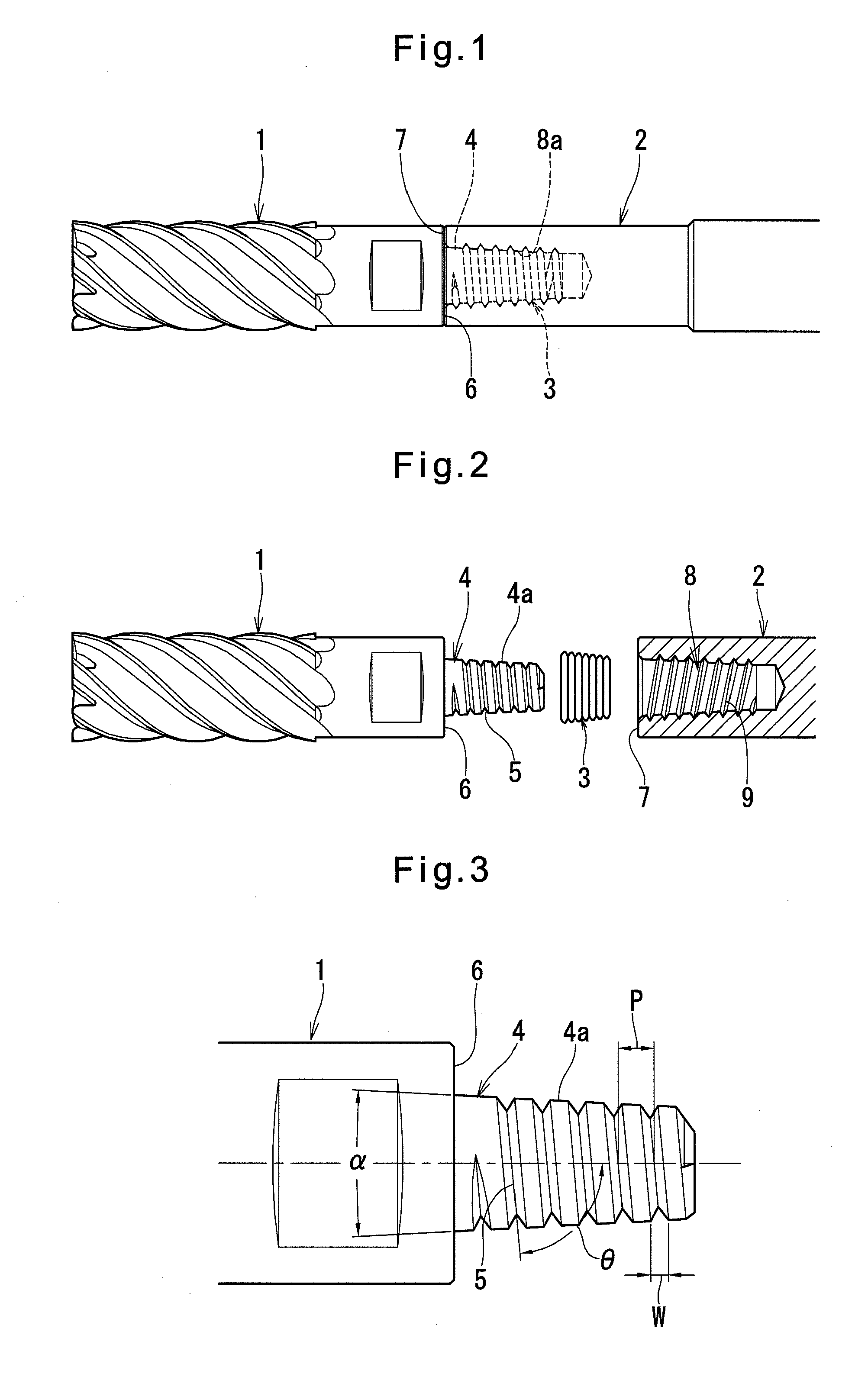
[0047]Now the cutting tool with a detachable head embodying the present invention is described with reference to FIGS. 1 to 8.

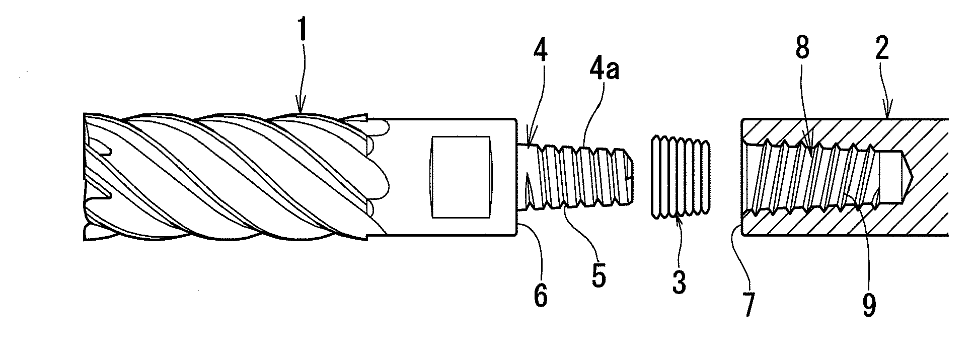
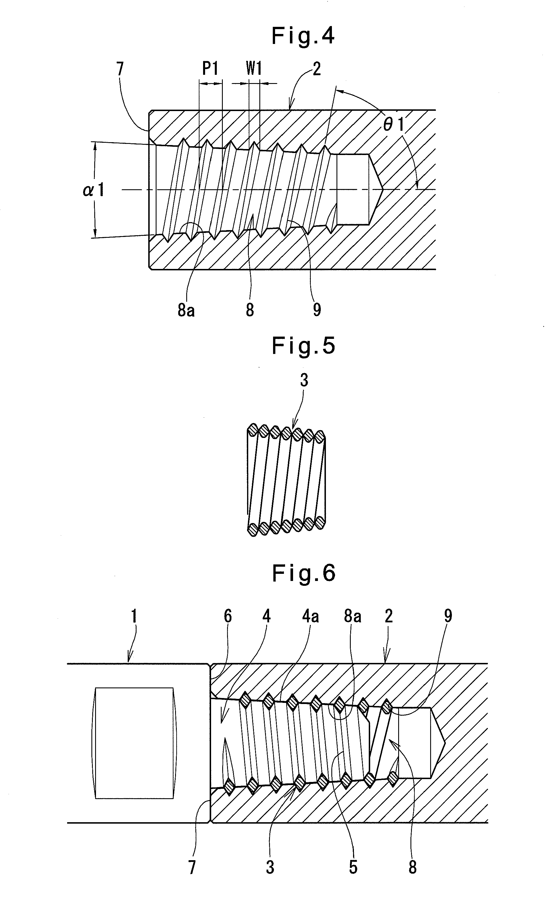
[0048]The cutting tool shown is a square end mill and includes a cutting head 1 having a peripheral cutting edge, an end cutting edge, a chip pocket, a gash, etc., a shank 2 to which the cutting head 1 is fastened, and a fastening attachment 3 that helps to securely fasten the cutting head 1 to the shank 2 and keep the cutting head fastened to the shank 2.

[0049]The cutting head 1 includes a tapered shaft portion 4 whose diameter decreases toward its distal end and which is formed with a helical flute 5 on its outer periphery. The cutting head 1 is further formed with a flat shoulder surface 6 extending radially outwardly from the proximal end of the tapered shaft portion 4.

[0050]The helical flute 5 has a helix angle θ shown in FIG. 3 and is arranged with a pitch P larger than the width W of the helical flute 5, thereby defining a tapered outer peripheral surf...


PUM


Abstract

A cutting head having a tapered shaft portion, a helical flute, and a flat shoulder surface is fastened to a shank having a front end surface, a tapered hole, and a helical flute through a fastening attachment in the form of a helical coil. The fastening attachment has a sectional shape substantially analogous in shape to a space defined between the helical flutes. The fastening attachment is fitted in one of the helical flutes, and is threaded into the other of the helical flutes until the shoulder surface is brought into close contact with the front end surface of the shank, and the outer peripheral surface of the tapered shaft portion is brought into close contact with the inner surface of the tapered hole, thus fastening the cutting head to the shank.

Description

TECHNICAL FIELD[0001]This invention relates to a cutting tool including a cutting head with cutting edges and shank, and further including an improved coupling by means of which the cutting head can be detachably fastened to the shank.BACKGROUND OF THE INVENTION[0002]Conventional cutting tools of this type are disclosed e.g. in the below-identified Patent documents:[0003]JP Patent Publication 2001-500801A[0004]JP Patent Publication 2001-505137A[0005]JP Patent Publication 2008-6508A[0006]JP Patent 4117131B[0007]The cutting tool disclosed in Patent document 1 (which is a ball end mill) includes an end mill head, a shank, and a pull rod which is in threaded engagement with both the end mill head and the shank. The end mill head and the shank have abutment surfaces, respectively, which are substantially perpendicular to the axis of the tool. The end mill head and the shank are fastened together by pulling them toward each other with the pull rod until their abutment surfaces abut each o...

Claims


Application Information

Patent Timeline
IPC IPC(8): B23C5/10
CPCB23C5/109B23B31/005B23B31/1115B23C5/10B23B2231/0204B23C2210/02B23C2210/03B23C2240/32Y10T407/192
Inventor MAEDA, KAZUOMORI, HIDEOKOUMOTO, NAOKIKAJIWARA, YASUHIRO
Owner SUMITOMO ELECTRIC HARDMETAL CORP
Why Eureka
Try Eureka