
Pyrolytic reactor

a technology of pyrolysis reactor and pyrolysis chamber, which is applied in the direction of mechanical vibration separation, pressurized chemical process, supercritical condition process, etc., can solve the problems of difficult thermal processing of acetylene from methane, non-uniform distribution,

Active Publication Date: 2014-02-27
UOP LLC
View PDF1 Cites 322 Cited by
  • Summary
  • Abstract
  • Description
  • Claims
  • Application Information

AI Technical Summary

Benefits of technology

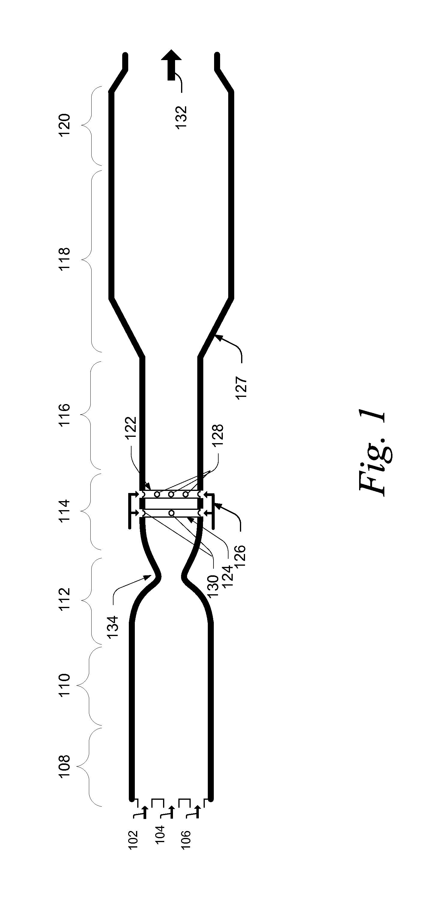
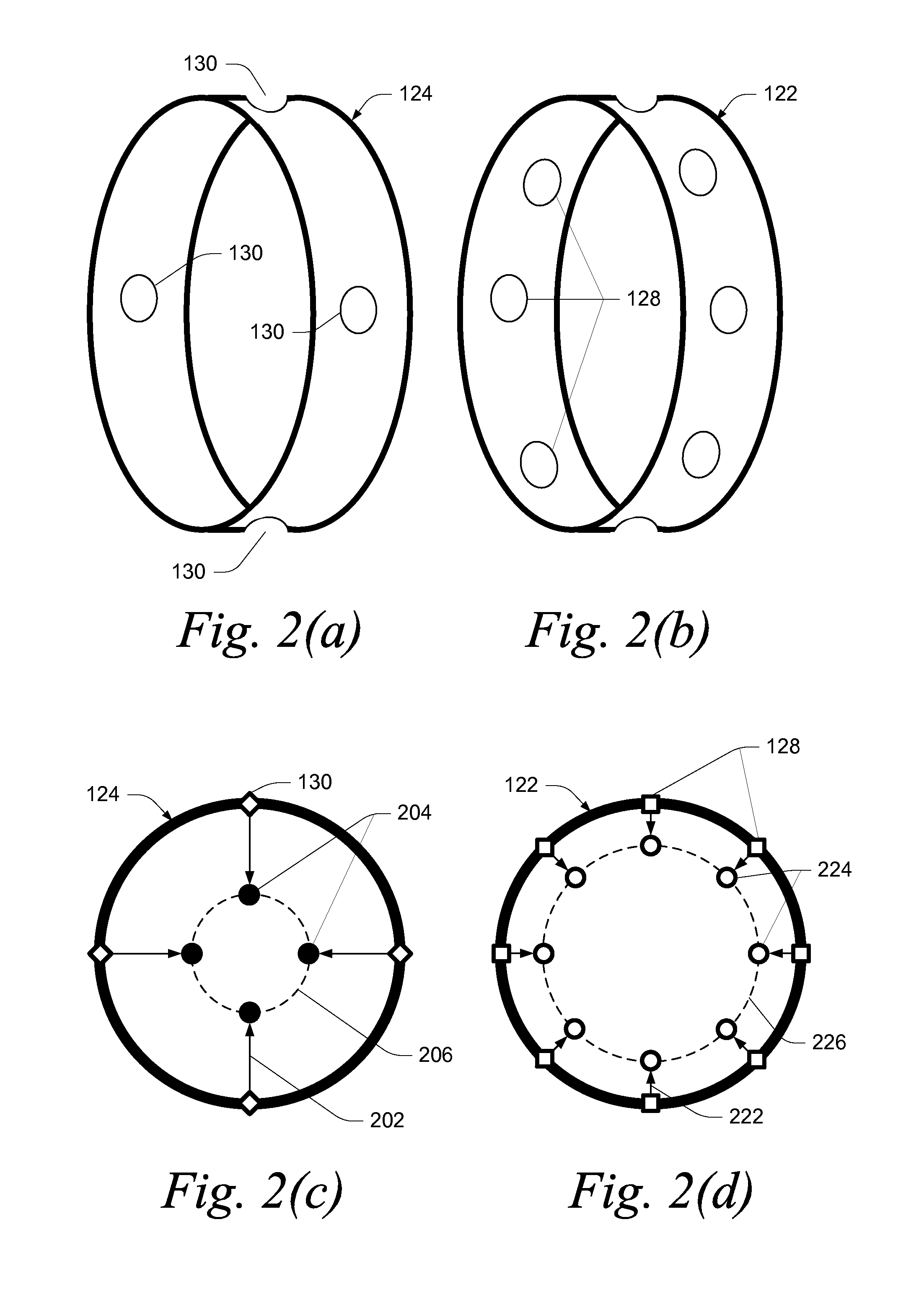
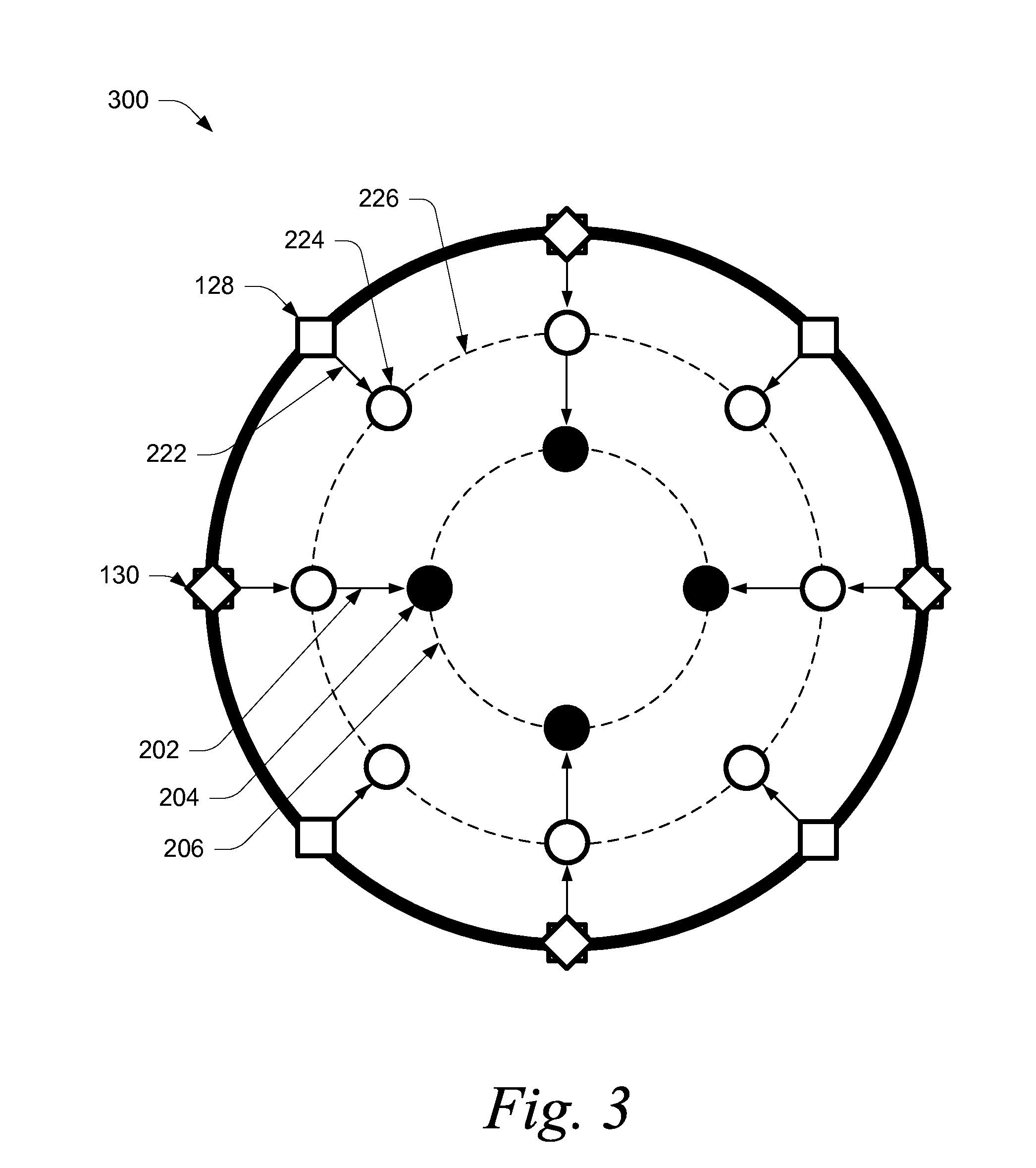
The patent describes a pyrolytic reactor that can convert feed material into a carrier gas. The reactor has multiple injection nozzles that are distributed in two planes. The first plane is located in the fuel injection zone, while the second plane is located in the combustion zone. The nozzles in the first assembly inject the feed material into the carrier stream at a specific depth, while the nozzles in the second assembly inject the feed material into the carrier stream at another specific depth. This design allows for better mixing of the feed material and carrier stream, resulting in more efficient and effective conversion.

Problems solved by technology

The formation of acetylene from methane by thermal processing is difficult because of the relative free energies of formation of methane and acetylene.
These prior art processes, however, rely on the turbulence of the stream to mix the feedstock within the carrier stream.
This creates a non-uniform distribution with a stream of highly concentrated, low temperature feedstock alongside the high temperature carrier stream.

Method used


Image

  • Pyrolytic reactor
  • Pyrolytic reactor
  • Pyrolytic reactor

Examples


Embodiment Construction

[0016]This invention is described in preferred embodiments in the following description with reference to the Figures, in which like numbers represent the same or similar elements. Reference throughout this specification to “one embodiment,”“an embodiment,” or similar language means that a particular feature, structure, or characteristic described in connection with the embodiment is included in at least one embodiment of the present invention. Thus, appearances of the phrases “in one embodiment,”“in an embodiment,” and similar language throughout this specification may, but do not necessarily, all refer to the same embodiment.

[0017]The described features, structures, or characteristics of the invention may be combined in any suitable manner in one or more embodiments. In the following description, numerous specific details are recited to provide a thorough understanding of embodiments of the invention. One skilled in the relevant art will recognize, however, that the invention may ...


PUM

PropertyMeasurementUnit
radial penetration depthaaaaaaaaaa
supersonic speedaaaaaaaaaa
subsonic speedaaaaaaaaaa

Abstract

A pyrolytic reactor comprising a fuel injection zone, a combustion zone adjacent to the fuel injections zone, an expansion zone adjacent to the combustion zone, a feedstock injection zone comprising a plurality of injection nozzles and disposed adjacent to the expansion zone, a mixing zone configured to mix a carrier stream and feed material and disposed adjacent to the feedstock injection zone, and a reaction zone adjacent to the mixing zone. The plurality of injection nozzles are radially distributed in a first assembly defining a first plane transverse to the feedstock injection zone and in a second assembly transverse to the feedstock injection zone.

Description

CROSS-REFERENCE TO RELATED APPLICATION[0001]This application claims priority from Provisional Application No. 61 / 691,376 filed Aug. 21, 2012, the contents of which are hereby incorporated by reference in its entirety.FIELD OF THE INVENTION[0002]The disclosure relates in general to a reactor for the pyrolytic processing of hydrocarbons. In certain embodiments, the disclosure relates to injectors to introduce feed material into the reactor. In certain embodiments, the disclosure relates to multiple assemblies of injectors configured to introduce feed material into different portions of the carrier stream within the reactor.BACKGROUND OF THE INVENTION[0003]Thermal processing techniques are commonly used to convert feedstock hydrocarbon material to more valuable products. For example, various thermal processing techniques are used to convert methane directly to C2 hydrocarbons, such as acetylene via reaction (1), ethylene via reaction (2), and ethane via reaction (3).2CH4→C2H2+3H2  (1)2...

Claims


Application Information

Patent Timeline
Patent Type & Authority Applications(United States)
IPC IPC(8): B01J3/00
CPCB01J3/008B01J6/008B01J19/02B01J19/2415B01J19/26B01J2219/0004B01J2219/00094B01J2219/00123B01J2219/00157B01J2219/0204B01J2219/0263B01J2219/0281B01J2219/0286B01J2219/029C07C2/78C07C11/24B01J4/002B01J2219/00051
Inventor STEVENS, CARL J.NEGIZ, ANTOINEKUCHANA, VINAYENDER
Owner UOP LLC
Learn More