Autonomous management of distribution transformer power load

Active Publication Date: 2014-02-27
EATON INTELLIGENT POWER LIMITED
View PDF14 Cites 21 Cited by
  • Summary
  • Abstract
  • Description
  • Claims
  • Application Information

AI Technical Summary

Benefits of technology

[0013]In another embodiment, the claimed invention includes a method of controlling power to an electrical load receiving power from a communicative distribution transformer communicating with a load-control device (LCD) associated with the electrical load. The method includes: sensing an operating characteristic of the communicative distribution transformer, the operating characteristic being indicative of a power load of a communicative distribution transformer; detecting that the operating characteristic indicative of the power load of the communicative distribution transformer exceeds a threshold; transmitting a load-management data message over a local network to a first load-control device (LCD) controlling a first electrical load receiving power from the communicative distribution transformer; receiving the load-management data message at the first LCD; and reducing the amount of power received by the first electrical load in response to the received load-management data message.
[0014]In an embodiment, the present invention comprises a load-managing electricity service (LMES) system for managing and controlling electricity-consuming loads supplied by a common distribution transformer. The LMES system includes: a communicative distribution transformer (CDT) sensor that includes a transceiver co

Problems solved by technology

If the distribution transformer is undersized in terms of its capacity to provide power to its connected residences and associated power-consuming devices, the transformer eventually fails, resulting in a temporary loss of power to those connected to the transformer, and eventual replacement of the existing transformer with a larger-capacity transformer.
Charging an electric vehicle consumes a relatively high amount of electricity in a relatively short period of time.
Although the actual power consumed depends on the particular vehicle and the extent of chargi

Method used


Image

  • Autonomous management of distribution transformer power load
  • Autonomous management of distribution transformer power load
  • Autonomous management of distribution transformer power load

Examples


Embodiment Construction

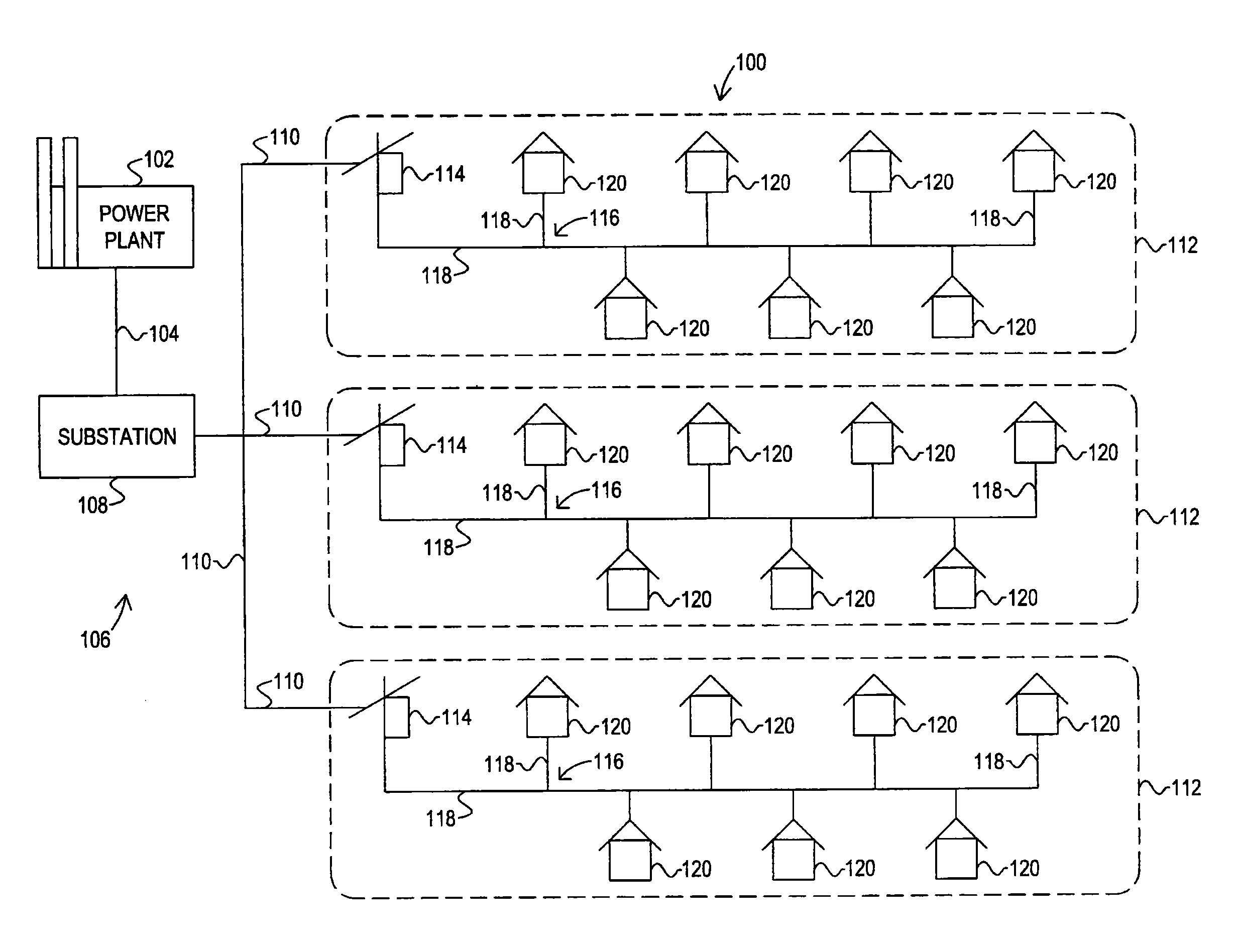
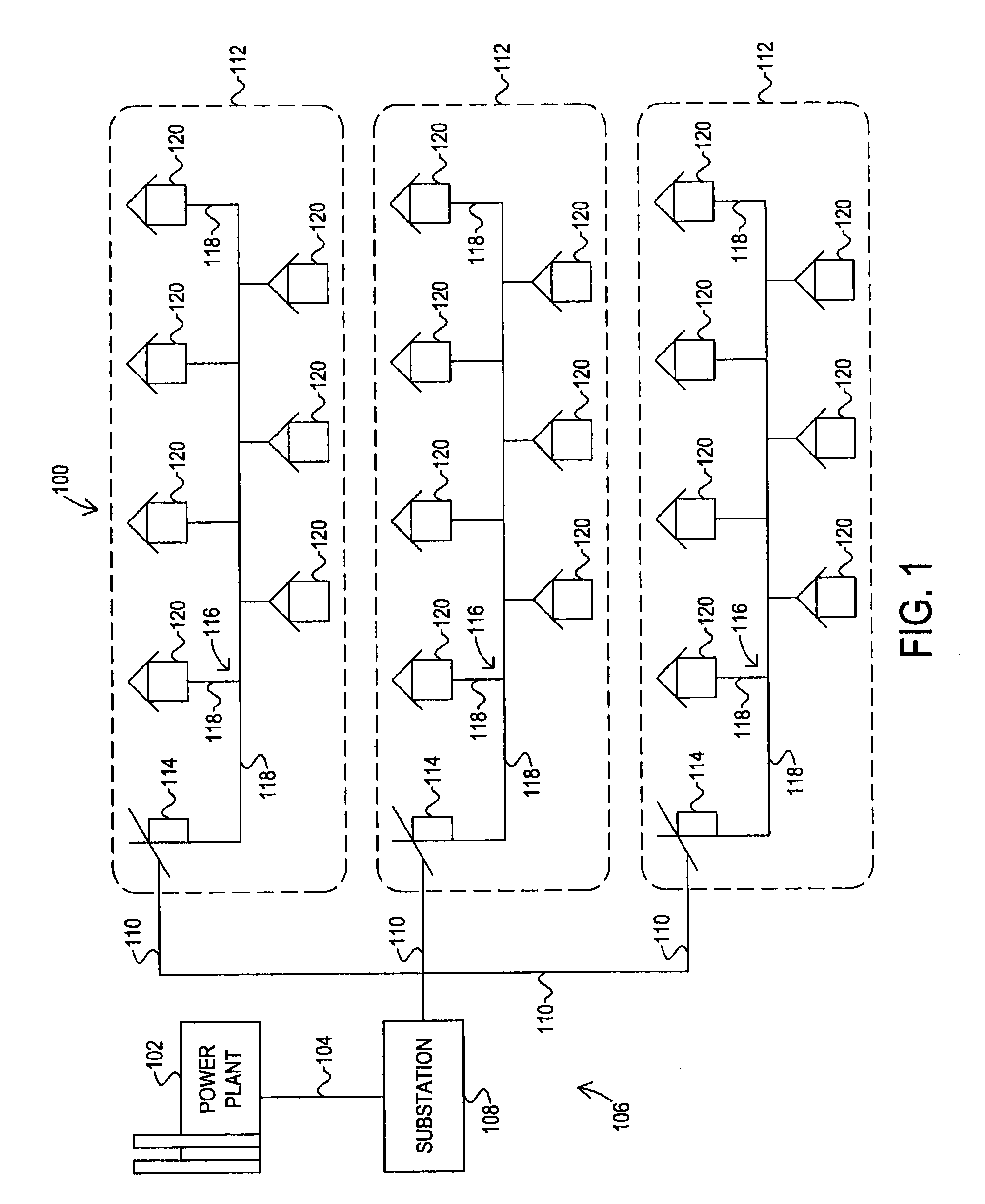
[0023]Referring to FIG. 1, in an embodiment, an electricity transmission and distribution grid 100 is depicted. Grid 100 includes a power plant, or electricity generation plant, 102, high-voltage transmission lines 104, and electricity distribution network 106. Power plant 102 generates electricity, transmits the electricity across a network of high-voltage transmission lines 104 to be distributed by distribution network 106.

[0024]Electricity distribution network 106, in an embodiment, includes one or more substations 108, distribution lines 110, and multiple electricity-service networks 112. Substations 108 receive the high-voltage electricity transmitted over transmission lines 104, and reduce the voltage of the electricity received over transmission lines 104, and transmit the reduced-voltage electricity over distribution lines 110 to local service networks 112 for further conditioning and distribution.

[0025]Each service network 112, in an embodiment, comprises distribution trans...


PUM


Abstract

A load-managing electricity service (LMES) system for managing and controlling electricity-consuming loads supplied by a common distribution transformer. The LMES system includes: a communicative distribution transformer (CDT) sensor that includes a transceiver, a sensing circuit and a processor configured to determine whether a power load of the transformer exceeds an upper threshold. The LMES system also includes a load-control device (LCD) configured to communicate with the CDT sensor, and to selectively decrease or increase the power load of the distribution transformer by managing the electricity-consuming leads at consumer premises.

Description

FIELD OF THE INVENTION[0001]The present invention relates generally to management and control of electrical loads.[0002]More particularly, the present invention relates to management and control of electrical loads connected to a distribution transformer.BACKGROUND OF THE INVENTION[0003]Electricity generated by a power plant is transmitted across a high-voltage transmission network to distribution networks for distribution to local businesses and residences. The high-voltage power is reduced by a substation for transmission across a distribution network that includes a series of distribution lines and distribution transformers. Whether the distribution lines are carried overhead by power poles, or buried underground, the voltage of the transmitted electricity on the distribution lines is typically reduced by a distribution transformer at or near the business or residence. In a residential neighborhood, a single distribution transformer typically serves four to eight residences, with...

Claims


Application Information

Patent Timeline
IPC IPC(8): G06F1/26
CPCY02T90/16B60L53/63Y02E60/00Y02T90/12Y02T10/70Y02T90/14Y04S10/126Y02T10/7072
Inventor ASHWORTH, NICHOLASCOX, ROBERT J.CHILDS, JOSEPH E.
Owner EATON INTELLIGENT POWER LIMITED
Why Eureka
Try Eureka