Buckling-Restrained Brace Assembly

a brace and buckling technology, applied in the direction of shock-proofing, manufacturing tools, building components, etc., can solve the problems of deformation, strength and stiffness reduction, performance degradation, etc., and achieve the effect of facilitating movement of steel cores and reducing friction

Active Publication Date: 2014-03-06
BLUESCOPE BUILDINGS NORTH AMERICA
View PDF10 Cites 27 Cited by
  • Summary
  • Abstract
  • Description
  • Claims
  • Application Information

AI Technical Summary

Benefits of technology

[0006]Flat steel plates and / or bar materials are used to create a unique configuration that is made up of a yielding steel core made from steel plate or bar as the load resisting element. The yielding steel core is confined against buckling between steel web plates welded to two steel flange plates in an “I” shape configuration. To limit the deformation of the steel core the web plates are placed in close proximity to the steel core, with only a very nominal gap provided by natural unevenness of the steel material. Additional friction reducing material, a liner or a thin coating may be applied to the steel core contact surfaces and to the surrounding web members to reduce friction and facilitate movement of the steel core

Problems solved by technology

When conventional structural braces are subject to high axial forces the braces may reach various forms of local and global buckling that can lead to reduced strength and stiffness, and degraded performance, even collapse, especially under cyclic loading resulting from an earthquake.

Method used


Image

  • Buckling-Restrained Brace Assembly
  • Buckling-Restrained Brace Assembly
  • Buckling-Restrained Brace Assembly

Examples


Embodiment Construction

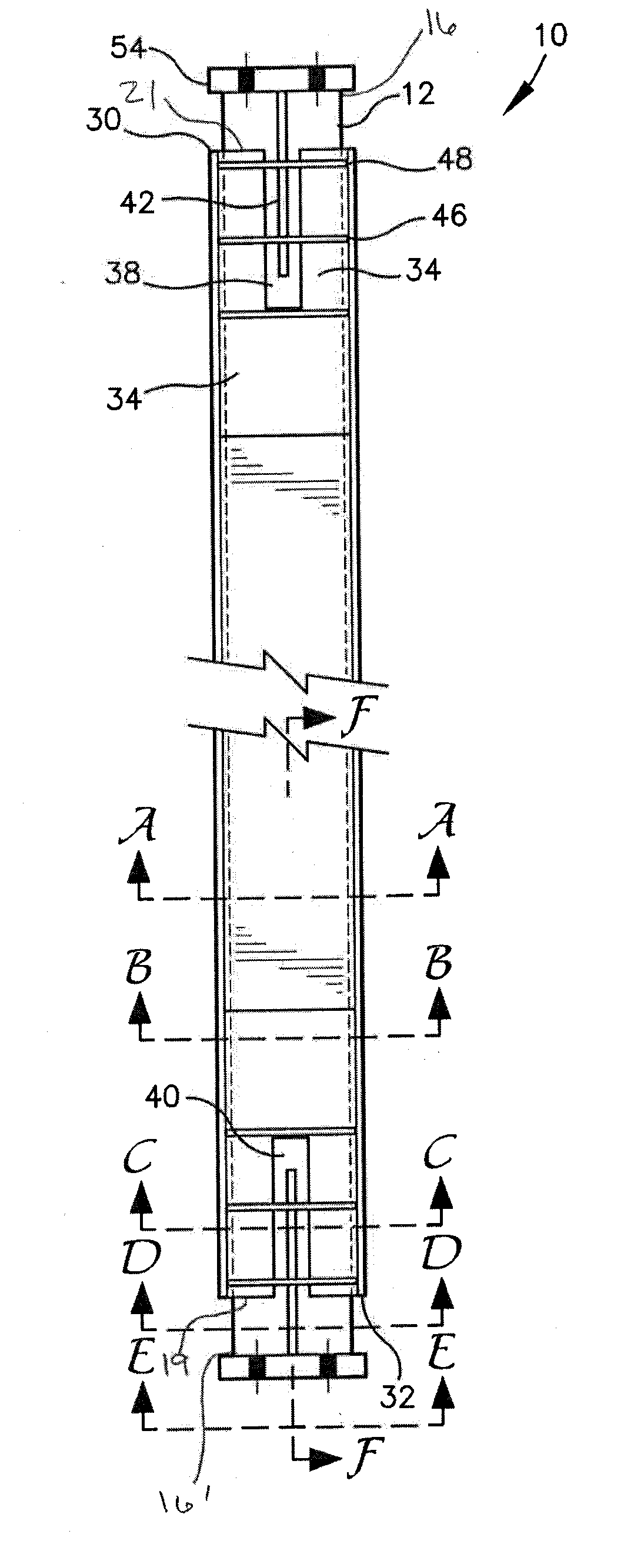
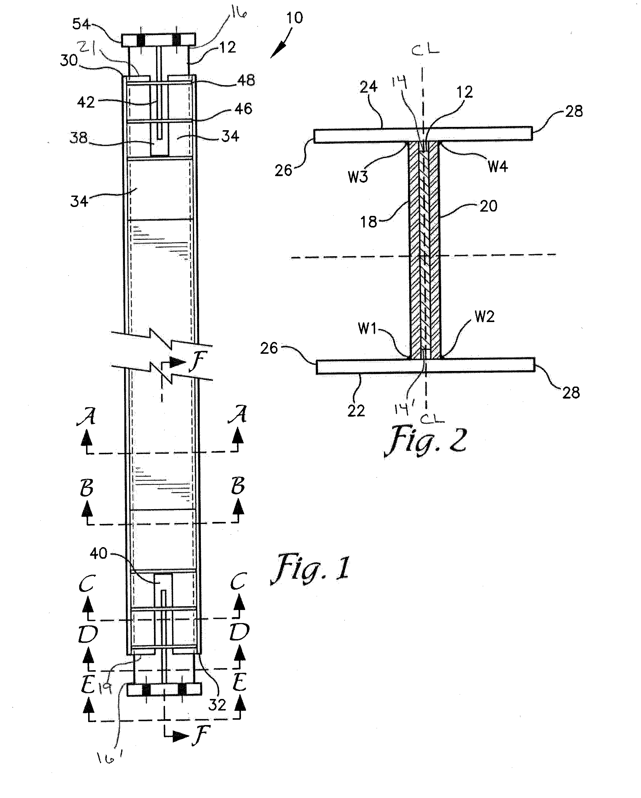
[0029]Referring now to the drawings wherein like reference numerals refer to similar or identical parts throughout the several views. FIG. 1 reveals a plan view of the brace assembly 10. As seen in FIGS. 1 and 2, the brace 10 is constructed with a core 12 with lateral edges 14, 14′ and longitudinal ends 16, 16′ sandwiched between an upper web 18 and a lower web 20. The core 12 and the upper and lower web 18, 20 are positioned perpendicularly, at approximately the centerline CL of the two parallel and opposed flanges 22, 24 with each flange having an upper edge 26 and a lower edge 28 and first and second longitudinal ends 30, 32. The upper and lower webs 18, 20 are secured to the parallel opposed flanges at weld lines W1, W2, W3 and W4.

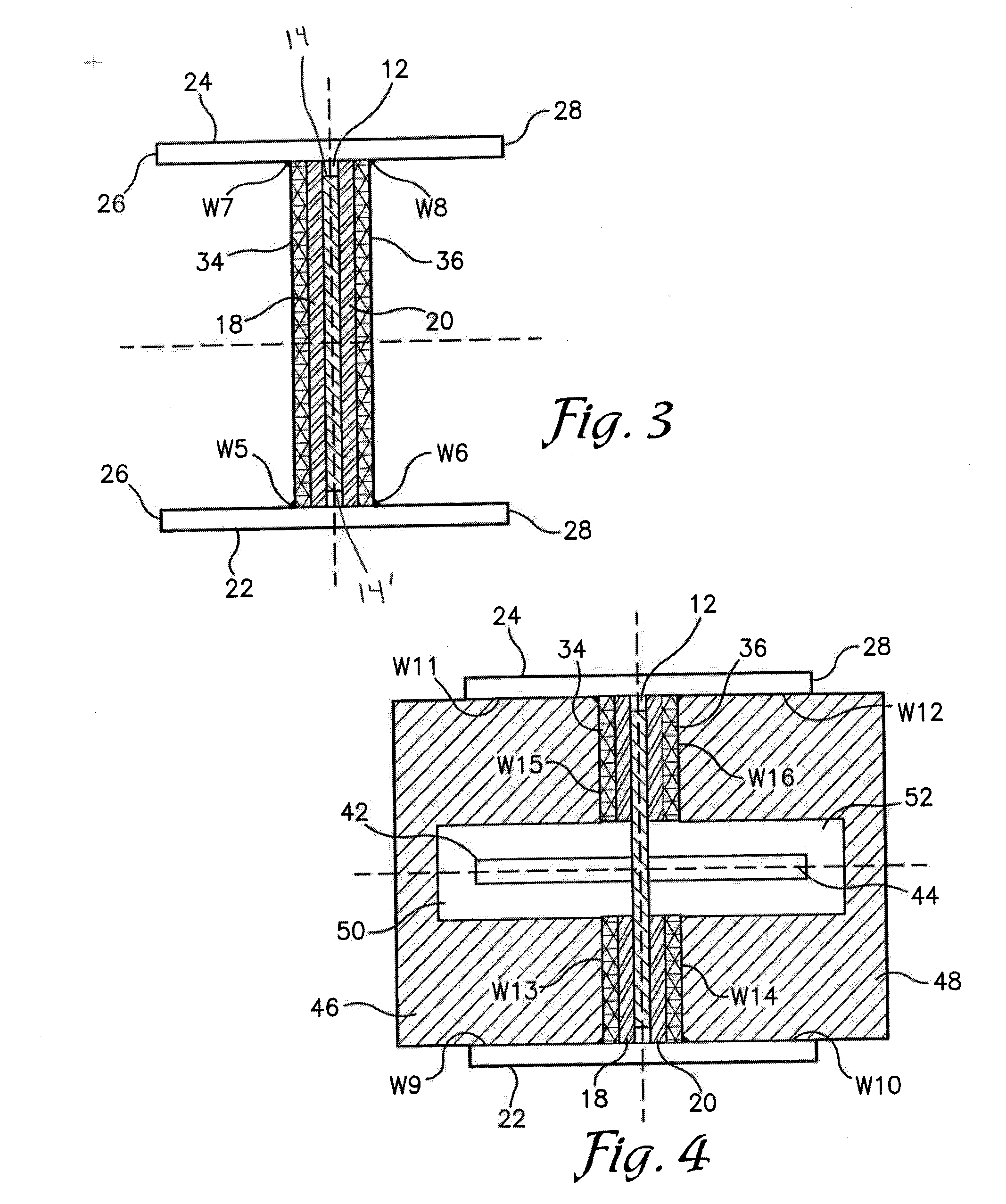
[0030]Both the upper web 18 and the lower web 20 each contain one small opening located mid-length between longitudinal ends 16, 16′ and equal distance between lateral edges 14, 14′ where a short weld is placed along the edge of the opening to secure t...


PUM

PropertyMeasurementUnit
brace anglesaaaaaaaaaa
forcesaaaaaaaaaa
lengthaaaaaaaaaa

Abstract

The disclosed subject matter is directed to a building structural bracing apparatus having an inner core element sandwiched between an upper and a lower containment web. The brace frame being useful in the construction of earthquake and blast resistant structures where energy dissipation is desired.

Description

CROSS-REFERENCE TO RELATED APPLICATIONS[0001]This application claims the benefit of priority to U.S. Provisional Application No. 61 / 697,646 filed on Sep. 6, 2012.BACKGROUND[0002]1. Field of the Invention[0003]The disclosed subject matter is directed to a bracing apparatus having a steel inner core element and the methods for fabrication of same. The present invention is useful in the construction of earthquake and blast resistant structures where energy dissipation is desired.[0004]2. Description of the Related Art[0005]Braced frames are commonly used in buildings and other structures to provide strength and stability against lateral forces induced by wind, earthquake, or other sources. Braced frames are also an effective solution for limiting lateral displacement of building stories. Regardless of the arrangement of braces in braced frames (diagonal, chevron, etc.), the overall strength and stability of the lateral-force resisting system depends mainly on the performance of the str...

Claims


Application Information

Patent Timeline
Patent Type & Authority Applications(United States)
IPC IPC(8): E04H9/02
CPCE04H9/028E04H9/021E04H9/0237E04H9/024
Inventor MARINOVIC, IGORHYDER, CLIFTON D.
Owner BLUESCOPE BUILDINGS NORTH AMERICA
Why Eureka
Try Eureka